Capacitance chromatography imaging type ice thickness detecting device and its detecting method

A technology of capacitance tomography and detection device, which is applied to electromagnetic measurement devices, measurement devices, and electromagnetic/magnetic thickness measurement, etc., to achieve the effects of being convenient to carry, low in cost, and improving measurement accuracy

Inactive Publication Date: 2008-07-16
TAIYUAN UNIV OF TECH
View PDF2 Cites 22 Cited by
  • Summary
  • Abstract
  • Description
  • Claims
  • Application Information

AI Technical Summary

Problems solved by technology

[0007] The invention adopts the mechanism of capacitance tomography technology, increases the sampling data by improving the structure of the capacitive

Method used


Image

  • Capacitance chromatography imaging type ice thickness detecting device and its detecting method

Examples


Embodiment 1

[0021] The specific implementation of the electrical capacitance tomography ice thickness detection device is as follows:

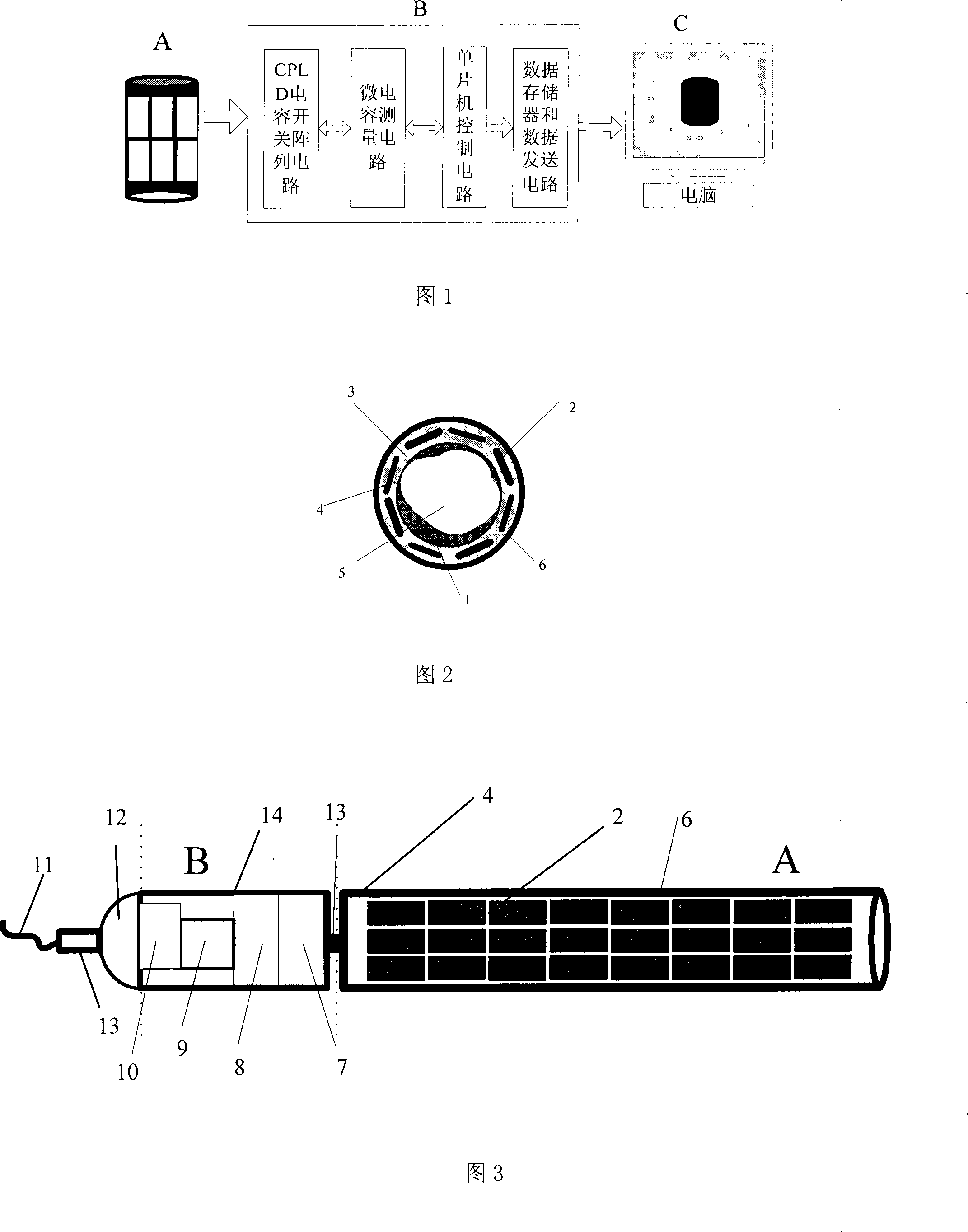
[0022] Fig. 3 is a multi-plate capacitance detection device, and Fig. 2 is a cross-sectional view of a capacitance sensor. On a hollow insulating tube 4 with a diameter of 30 mm, 6 to 10 (preferably 8) are evenly arranged radially along the outer surface of the hollow insulating tube 4 from one end with an axial length of 60 mm and a thickness of 3 mm. The metal copper plate is the capacitor plate 2, which constitutes a group of capacitor banks (the number of capacitor plates specifically set is related to the inner diameter of the hollow insulating tube, the measurement accuracy and the measured object, etc.). Then according to the needs of the detection of the thickness of the ice layer to be measured, the same two or more sets of multi-plate capacitor banks are evenly arranged along the outer surface of the hollow insulating tube 4 in sequence, and eac...

Embodiment 2

[0024] The detection method using the electrical capacitance tomography ice thickness detection device is as follows:

[0025]Place the capacitive sensor A shown in Figure 2 vertically downwards in the water (generally, a rubber float is set on the top of the sensor or a hole can be drilled for installation when the ice thickness is already more than 20mm). During the measurement, the power supply is turned on, and the single-chip microcomputer control circuit 9 in the signal acquisition and data processing module B part sends detection instructions and control signals, and the control signals pass through the CPLD switch array circuit 7 to strobe two capacitors in the first group of capacitor banks from top to bottom. The capacitor plates 2 form a capacitor, and the capacitance value of the capacitor is measured and stored; the capacitance values ​​of the capacitors in the group composed of other capacitor plates 2 are measured and stored in turn. Then carry out the same meas...


PUM


Abstract

The invention relates to a capacitance tomography ice-thickness measuring device and a measuring method. The invention is characterized in that a multi-electrode capacitance sensor is designed to be integrated with a signal collecting and data treating module; the multi-electrode capacitance sensor is formed by equally arranging a plurality of capacitance electrodes along both radial and axial directions on the circle surface of a hollow insulation pipe, and metal shield tube is sheathed at the outer surface of the capacitance electrode; the signal collecting and data treating module integrates a CPLD switch array circuit, a micro-capacitance measuring circuit, an SCM control circuit, a data storing and sending circuit into a whole. When in use, the device is vertically arranged in the water area or ice layers to be measured, and a power supply is switched on to carry out the capacitance value measuring and storing; after measuring, the data is input into a computer and a capacitance tomography calculation drawn by a two-dimensional section three-body is adopted to carry out computer imaging process so as to calculate the thickness of the ice layers. The invention has simple structure, low manufacturing cost and high automatization level. The invention can be applied to an automatic and continuous measuring to various ice layer thicknesses and a generation and disappearing process of frozen earth layers.

Description

technical field [0001] The invention relates to a device and a detection method for automatic detection of ice layer thickness generation and disappearance process, in particular to a method of using electrical capacitance tomography technology to monitor various ice layer thicknesses and the generation and disappearance process of frozen soil layers in cold regions in low temperature environments. A fixed-point automatic continuous detection device and a detection method. technical background [0002] Electrical capacitance tomography technology is currently mainly used in the detection and control of industrial two-phase flow. However, due to the different industrial field environments, the design methods of capacitance tomography technology in microcapacitance detection circuit and imaging algorithm are different. According to the technical mechanism of electrical capacitance tomography, combined with the existing ice layer thickness detection device and detection method...

Claims


Application Information

Patent Timeline
IPC IPC(8): G01B7/06G01B21/08G08C17/00
Inventor 窦银科常晓敏马福昌曹凤才
Owner TAIYUAN UNIV OF TECH
Why Eureka
Try Eureka