
Main mirror face deformation detecting method and system for space reflection type optical remote sensor

A technology of optical remote sensor and detection system, which is applied in the direction of testing optical performance, etc., can solve the problems of prolonged detection time, heavy weight, not very suitable for space optical remote sensor, etc., and achieve the effect of strong concealment and low energy consumption

Inactive Publication Date: 2008-07-16
BEIJING INSTITUTE OF TECHNOLOGYGY
View PDF0 Cites 4 Cited by
  • Summary
  • Abstract
  • Description
  • Claims
  • Application Information

AI Technical Summary

Problems solved by technology

However, this method needs to install a mechanical scanning device not smaller than the aperture of the primary mirror outside the primary mirror. The structure is relatively complex, the weight is heavy, and the detection time is prolonged due to the use of sequential scanning, which is not very suitable for space optical remote sensors.

Method used


Image

  • Main mirror face deformation detecting method and system for space reflection type optical remote sensor
  • Main mirror face deformation detecting method and system for space reflection type optical remote sensor
  • Main mirror face deformation detecting method and system for space reflection type optical remote sensor

Examples


Embodiment Construction

[0035] Below in conjunction with accompanying drawing, concrete implementation of the present invention is described in further detail:

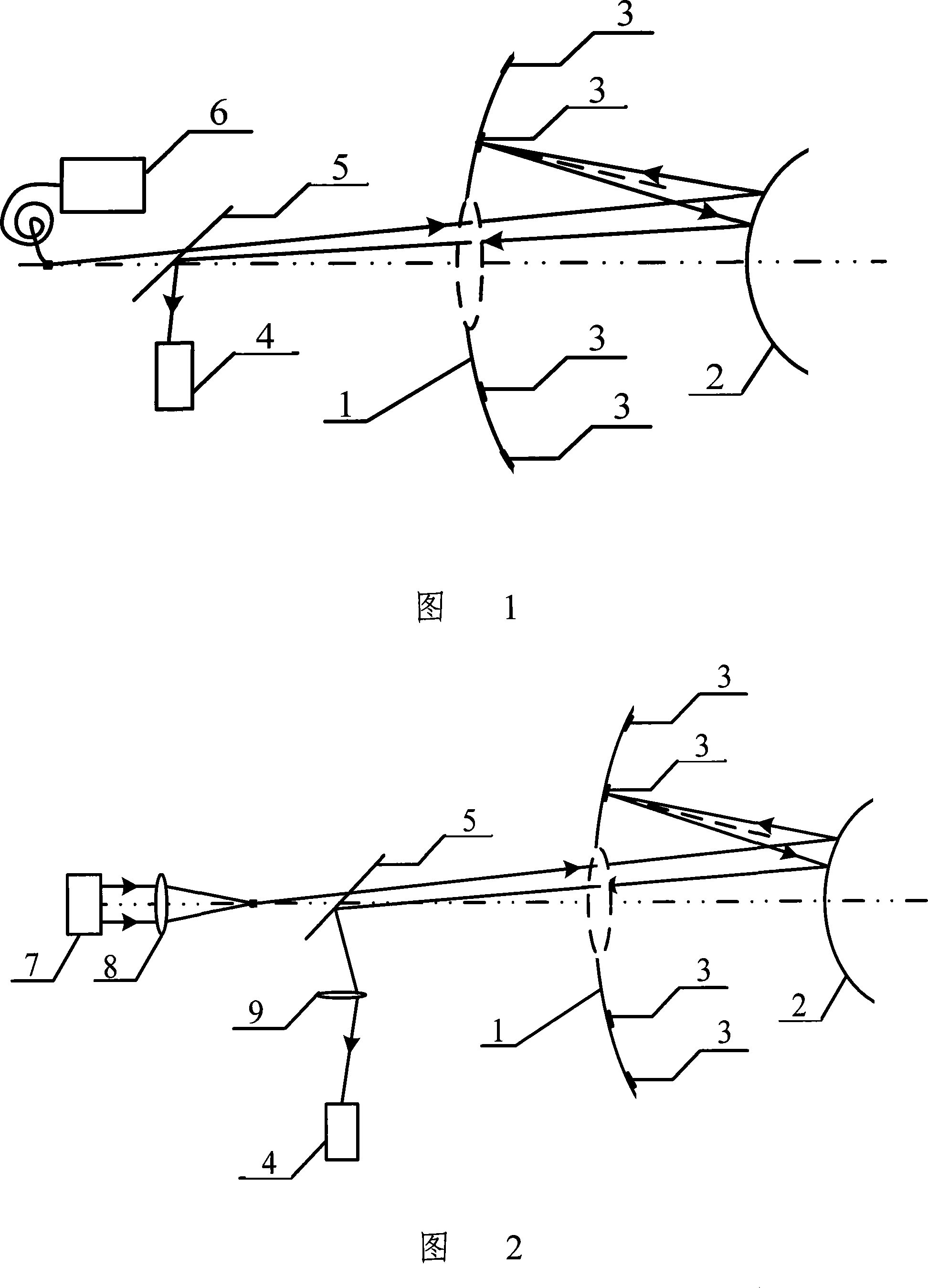
[0036]The basic idea of ​​the present invention is: a point light source device is set inside the spatial reflective optical remote sensor as a beacon, and fixed on or near the main mirror surface of the spatial reflective optical remote sensor according to the requirements of measurement accuracy and the requirements of the Nyquist sampling theorem. Multiple sampling mirrors, at the same time fix the secondary mirror in front of the main mirror of the spatial reflective optical remote sensor, fix the beam splitter and the detection device between the point light source device and the primary mirror, and arrange the positions of each device so that the primary mirror is in normal Under normal circumstances and when distortion occurs, the point light source device can be detected by the detection device through the reflection of the secondary ...


PUM


Abstract

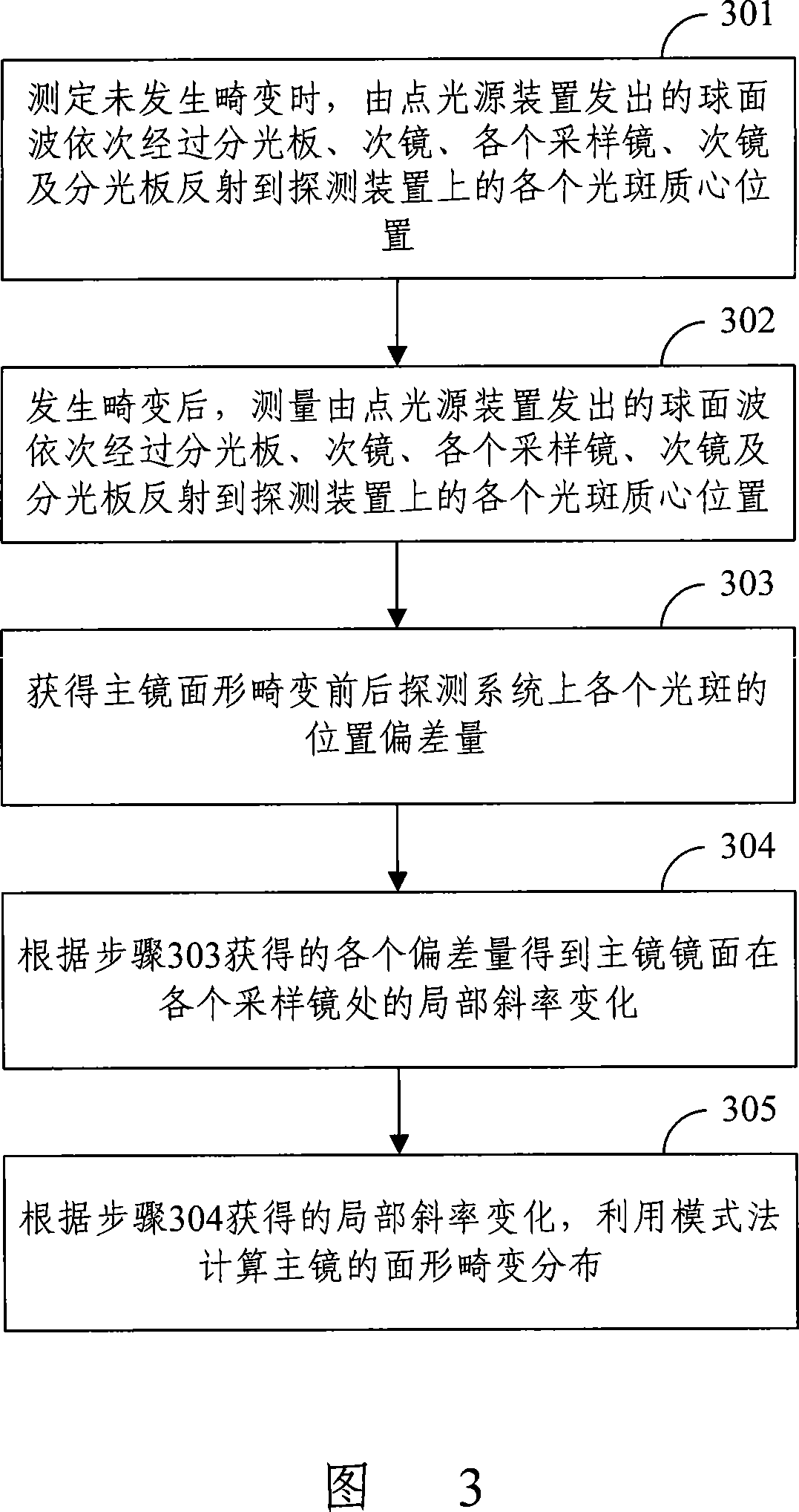
The invention discloses a space reflecting type optical remote sensor main mirror surface shape aberrance detecting system. The system includes a main mirror, secondary mirrors, a pointolite device, beam-splitters, sampling mirrors and a photoelectric detecting device; wherein, the system is provided with a plurality of the sampling mirrors and the sampling mirrors are all rigidly connected with the main mirror. The invention simultaneously discloses a space reflecting type optical remote sensor main mirror surface shape aberrance detecting method which detects the centroid positions of each facula formed by that the pointolite passes through the beam-splitter, the secondary mirror, the plurality of sampling mirrors, the secondary mirror and the beam-splitter sequentially and is reflected on the detecting device before and after the main mirror surface generates aberrance to acquire the deviation value of the centroid positions of each facula before and after the aberrance of the main mirror surface; the partial slope change of the main mirror at the location of each sampling mirror is calculated according to the deviation value; thereby acquiring the distribution of the main mirror surface shape aberrance. By utilizing the invention, the main mirror surface shape aberrance can be led to have the advantages of few limitations, little energy consumption, high concealment; and the invention can provide enough signal-to-noise ratio, the structure needs detecting is simple and reliable and the detecting process is simple and convenient.

Description

technical field [0001] The invention relates to a detection technology of the main mirror surface distortion of a reflective optical imaging system, in particular to a detection method and system for the main mirror surface distortion of a spatial reflection optical remote sensor. Background technique [0002] With the development of space science and technology, space optical remote sensors are playing an increasingly important role in the acquisition of ground information. For example, space optical remote sensors can be used for forest fire early warning, weather forecasting, crop monitoring, and especially space reconnaissance. etc. The space optical remote sensor has the advantages of wide monitoring range, high resolution, and strong real-time performance. It is a modern, high-performance, and non-territorial space monitoring tool. It has become a space project that various countries are competing to develop. [0003] In practical applications, due to factors such as ...

Claims


Application Information

Patent Timeline
IPC IPC(8): G01M11/02
Inventor 赵达尊王潇毛珩王欣胡新奇朱秋东俞信
Owner BEIJING INSTITUTE OF TECHNOLOGYGY
Learn More