Optical strain gauge strips

A strain gauge and optical technology, applied in the field of optical strain gauges, to achieve the effect of saving distance, high repeatable manufacturing accuracy, and saving structural space

Inactive Publication Date: 2008-07-23
HOTTINGER BALDWIN MESSTECHNIK GMBH
View PDF1 Cites 6 Cited by
  • Summary
  • Abstract
  • Description
  • Claims
  • Application Information

AI Technical Summary

Problems solved by technology

But the waveguide connecting section between the Bragg gratings is obviously still significantly longer than the Bragg grating itself which measures the strain, the Bragg grating already needs about 10mm in length

Method used


Image

  • Optical strain gauge strips
  • Optical strain gauge strips

Examples


Embodiment Construction

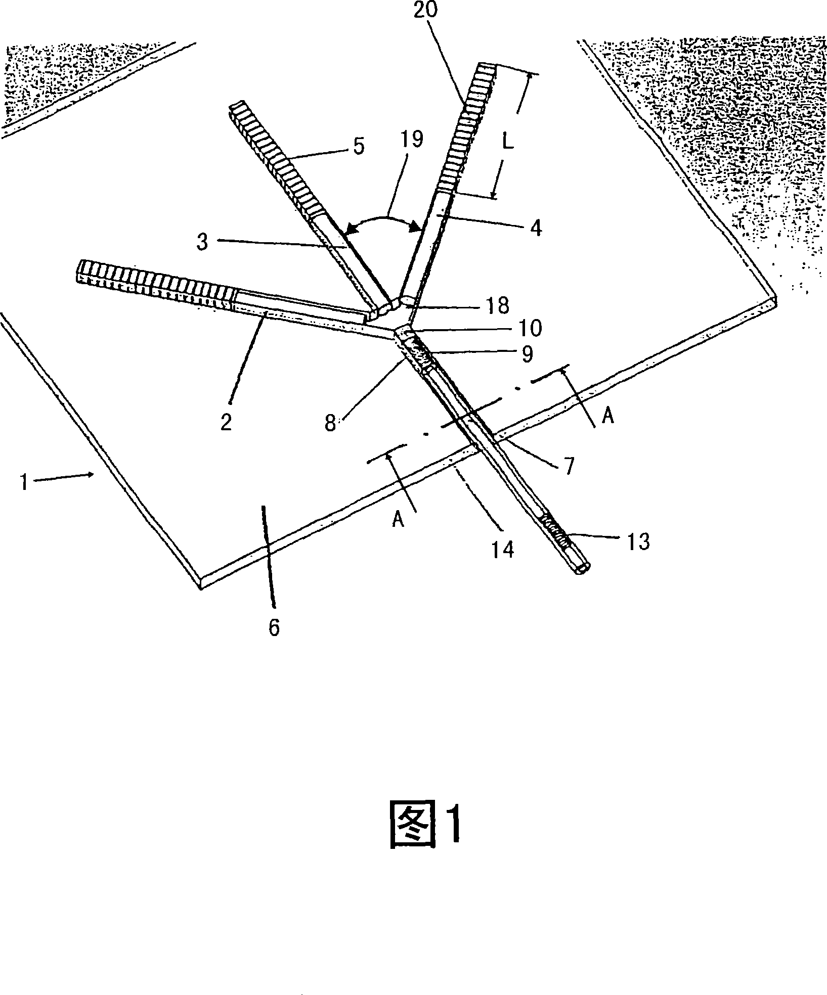
[0017] FIG. 1 shows an optical strain gauge 1 which is designed as a rosette for two-axis strain measurement and consists of three measuring waveguide sections 2 , 3 , 4 arranged next to each other with pressed Bragg gratings 5 ​​. , they are fed by the feed waveguide 7, and the light wave signal of the feed waveguide is transmitted through the ray expansion element 8.

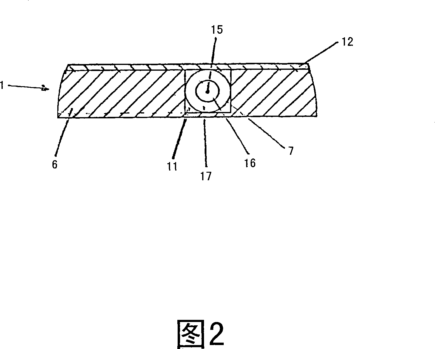
[0018] The optical waveguides 2 , 3 , 4 are all designed as straight sections and are embedded in a common carrier layer 6 , which is designed as a carrier film. In this case, the waveguide sections consist of a feed waveguide and three further sections of the measuring waveguide 2 , 3 , 4 with preferably pressed Bragg gratings 5 ​​. For receiving the optical waveguides 2, 3, 4, a thin carrier film 6 is provided, which preferably consists of a hard and elastic plastic such as polyamide. However, the carrier film 6 can also be made of other hard elastic plastics, glass, ceramic or metal. In this case, the car...


PUM

PropertyMeasurementUnit
diameteraaaaaaaaaa

Abstract

The invention relates to an optical strain gauge strip (1) for multi-axis strain measurement, comprising at least two straight optical fibre sections (2, 3, 4) with Bragg gratings (5), arranged adjacent to each other at a given angle (19) of 90 DEG or 45 DEG on a support layer (6) and supplied with light waves from a common injection optical fibre section (7). The invention is characterised in that all optical fibre sections (2, 3, 4, 7) are preferably provided on the support layer (6) in straight lines and a beam dispersion element (8) is arranged between the injecting optical fibre section (7) and the measuring optical fibre sections (2, 3, 4) with the Bragg grating (5).

Description

technical field [0001] The present invention relates to an optical strain gauge for detecting multi-axial strain according to the preamble of claim 1 and a method for manufacturing the optical strain gauge according to the preamble of claim 11 . Background technique [0002] For the analysis of calculated forces in measuring technology or for the monitoring of mechanically loaded components, electronic strain gauges are frequently used which detect the strain of the stressed structural element. These electronic strain gauges usually consist of a meander-shaped measuring grid of resistive material produced by photoetching, which is applied to a plastic carrier film and is usually covered with another plastic protective film for mechanical protection. To detect load-dependent strain, these electronic strain gauges are applied to the deformable body and convert the strain into an electrical signal, which is proportional to the strain or applied force, by measuring the change in...

Claims


Application Information

Patent Timeline
Patent Type & Authority Applications(China)
IPC IPC(8): G01L1/24
CPCG01L1/246
Inventor K-H·哈泽M·施密特R·布林
Owner HOTTINGER BALDWIN MESSTECHNIK GMBH
Why Eureka
Try Eureka