Continuous rolling mill entrance region tight rolls system and control method thereof

A control method and technology of the entry section, which are applied in the rolling mill control device, metal rolling, tail end control, etc., can solve the problems of great influence on the quality and yield, achieve the protection of the surface of the tension roll, avoid the sliding phenomenon, improve the The effect of yield

Active Publication Date: 2008-07-30
BAOSHAN IRON & STEEL CO LTD
View PDF0 Cites 9 Cited by
  • Summary
  • Abstract
  • Description
  • Claims
  • Application Information

AI Technical Summary

Problems solved by technology

However, over the years, the scratches at the entrance section of the strip accounted for about 1.2% of the total strip steel pro

Method used


Image

  • Continuous rolling mill entrance region tight rolls system and control method thereof
  • Continuous rolling mill entrance region tight rolls system and control method thereof
  • Continuous rolling mill entrance region tight rolls system and control method thereof

Examples


Embodiment Construction

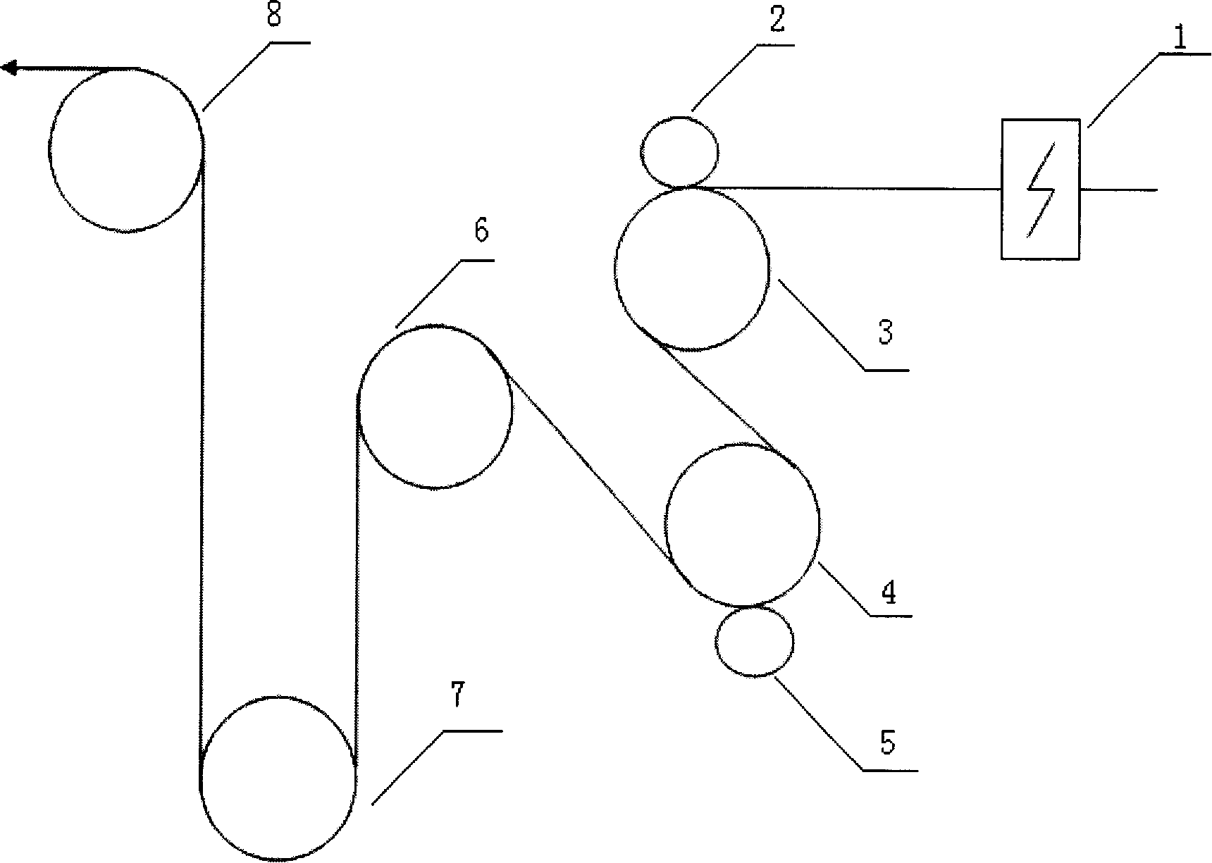
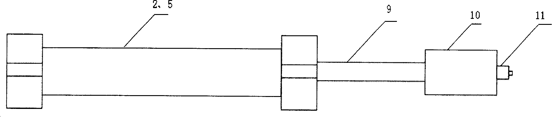
[0028] Depend on figure 1 and figure 2 It can be seen that the tension roller group system of the present invention includes: welding machine 1, 1# pressure roller 2, 1# tension roller 3, 2# tension roller 4, 2# pressure roller 5, 3# tension roller 6, 4# Tension Roller 7, 1# Control Roller 8, Electric Motor 10, Connecting Rod 9, Encoder 11.

[0029] The electric motor 10 is connected to the pressure roller 2 and the pressure roller 5 through the connecting rod 9 to provide torque for the pressure roller 2 and the pressure roller 5, and the electric motor 10 is also connected to an encoder 11 . The present invention uses an electric motor as the power device, and of course other power devices can also be used, and the power device is connected to the control system through the PROFIBUS DP network to control the torque and speed of the pressure roller power device. Adjust the speed and torque of the pressure roller according to the speed, tension of the looper, and the workin...


PUM


Abstract

The invention discloses a tension roll group system at entrance of a continuous rolling mill and a control method thereof. The tension roll group system consist of a tension roll, a press roll and an auto control system used for controlling the tension roll group system at the entrance of the continuous rolling mill. The press roll is connected with a power device. The invention changes the press roll of the tension roll into belt drive control and controls the tension roll system through the control method which is to adjust speed and torque of the press roll according to the speed, loop tension and the working status of the equipment at the entrance of a continuous rolling mill, prevent strip from sliding at the tension roll group and protect the surface quality of the strip and the surface of the tension roll, thereby reducing scratching of the strip tail.

Description

technical field [0001] The invention relates to a continuous rolling mill system with a looper and its control method, in particular to a tension roller group system and its control method at the entrance section of the continuous rolling mill. Background technique [0002] The cold rolling 2030 C102 unit is a continuous rolling system, and the entrance section is a double uncoiling system. After passing through the public section, it reaches the welding machine. After the welding is completed, the strip is temporarily stored through the looper to feed the rolling mill. In the uncoiler area, it mainly produces steel plates for home appliances such as automobile plates and refrigerator plates, and has relatively high quality requirements for strip steel. However, over the years, the scratches at the entrance section of the strip accounted for about 1.2% of the total strip production, and were divided into two parts: the leading and the trailing scratches, which had a great im...

Claims


Application Information

Patent Timeline
IPC IPC(8): B21B39/08B21B37/72B21B37/00
Inventor 陈虎王瑞庭黄佩杰黄春华施汉杰
Owner BAOSHAN IRON & STEEL CO LTD
Why Eureka
Try Eureka