

Light scattering slice and preparation method thereof
A technology of a light diffusing sheet and a manufacturing method, which is applied to optics, optomechanical equipment, nonlinear optics, etc., can solve the problems of uneven coating of the diffusing film, decreased efficiency, decreased light transmittance, etc., and achieves convenient and reliable manufacturing process. , soft and comfortable light, flexible processing technology
- Summary
- Abstract
- Description
- Claims
- Application Information
AI Technical Summary
Problems solved by technology
Method used
Image

Examples
Embodiment 1
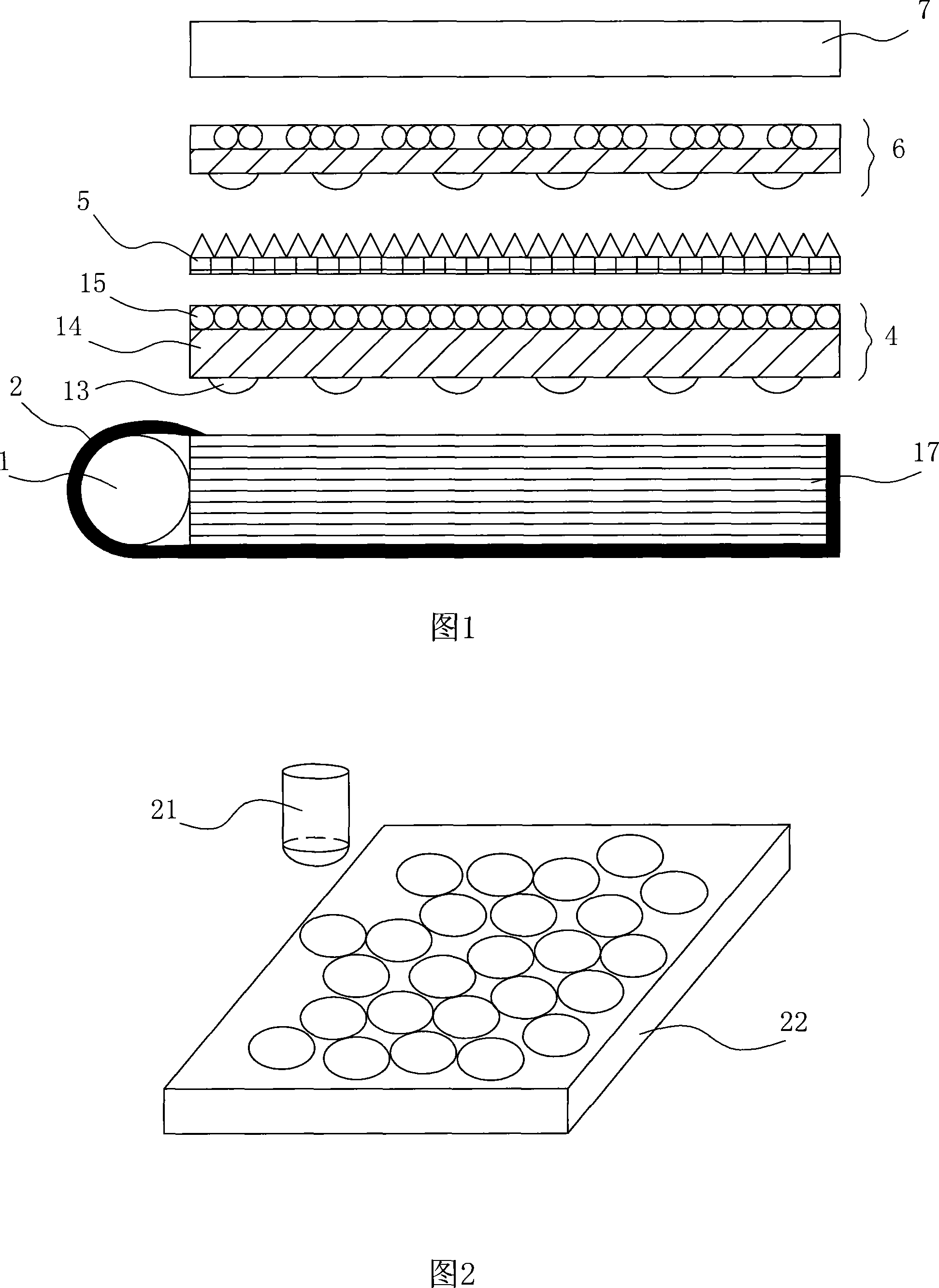
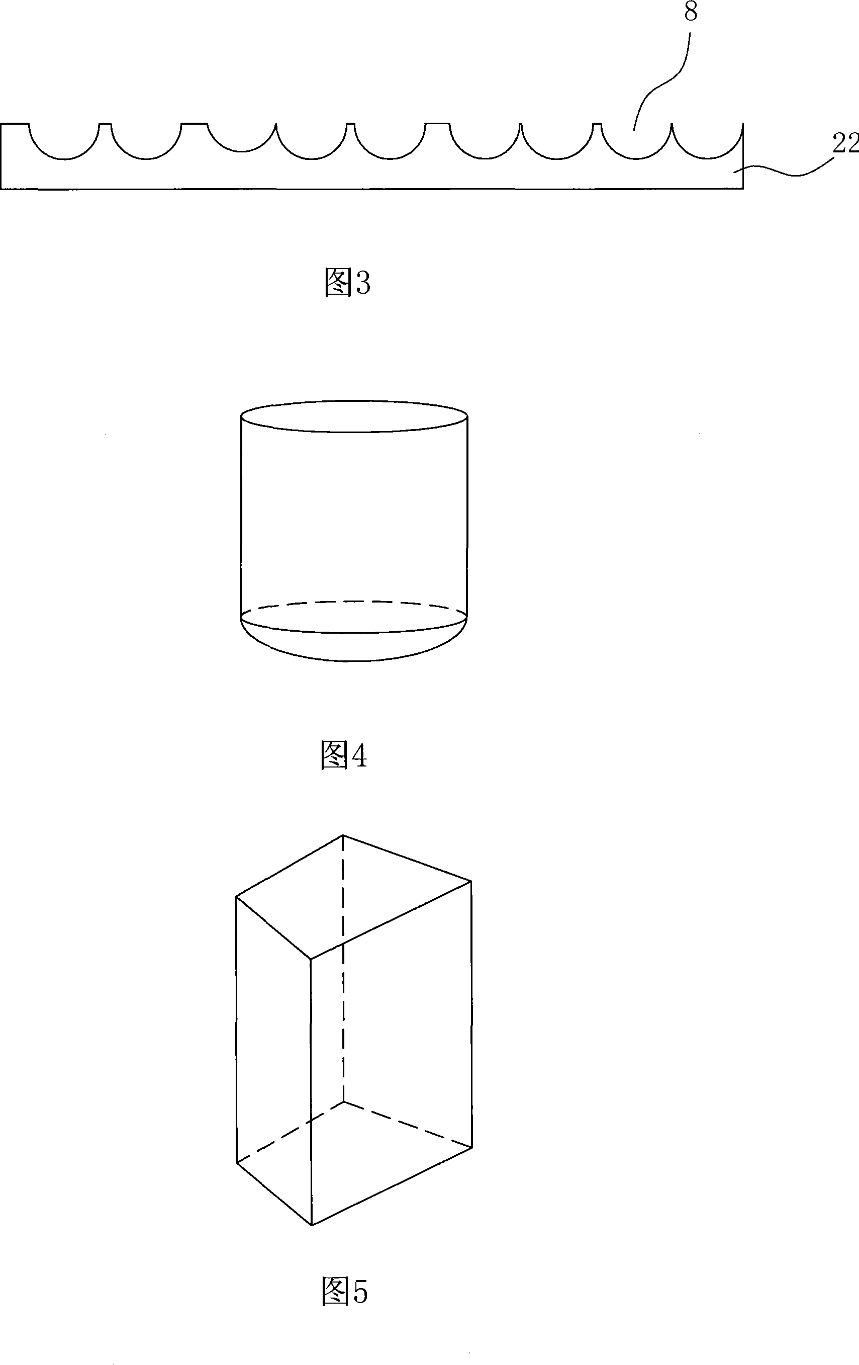
[0042] Embodiment 1: Referring to Fig. 1 to Fig. 5, (1) making an embossing mold core having at least one microlens structure;
[0043] (2) Set the computer embossing control program, embossing parameters and graphic files;
[0044] (3) Using the method of micro-nano thermal embossing or ultraviolet imprinting, emboss the embossing core in step (1) on the substrate to be imprinted according to the embossing parameters and graphic files in step (2). At the first embossing position of the material, the base material obtains a corresponding number of concave micro-lenses;
[0045] (4) According to the embossing parameters, change the relative position of the embossing mold core and the substrate to be imprinted to the next embossing station;
[0046] (5) Steps (3) and (4) are repeated until all imprinting procedures are completed.
[0047] As shown in Figure 2, the embossing mold core 21 has a hemispherical shape, and the base material 22 of the diffusion sheet to be imprinted ...
Embodiment 2
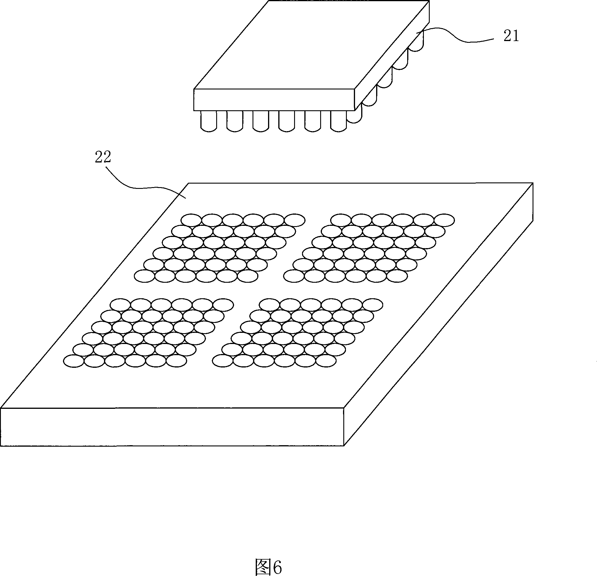
[0059] Embodiment 2: Referring to Fig. 6, (1) making an embossing mold core having at least one microlens structure;
[0060] (2) Set the computer embossing control program and parameter graphic files;
[0061] (3) Using the method of micro-nano thermal embossing or ultraviolet imprinting, emboss the embossed core in step (1) on the substrate to be imprinted according to the control program and graphic file in step (2) At the first embossing working position, the base material obtains a corresponding number of concave microlenses;
[0062] (4) According to the control program, change the relative position of the embossing mold core and the substrate to be imprinted to the next embossing station;
[0063] (5) Steps (3) and (4) are repeated until all imprinting procedures are completed.
[0064] In this embodiment, the embossing mold core 21 is composed of a plurality of microlens structures arranged in a 6×6 array combination. The methods for realizing the preset microlens ar...
Embodiment 3
[0067] Embodiment 3: Referring to Fig. 7 to Fig. 9, (1) making an embossing mold core having at least one microlens structure;
[0068] (2) Set the computer embossing control program and parameter graphic files;
[0069] (3) Using the method of micro-nano thermal embossing or ultraviolet imprinting, emboss the embossed core in step (1) on the substrate to be imprinted according to the control program and graphic file in step (2) At the first embossing working position, the base material obtains a corresponding number of concave microlenses;
[0070] (4) According to the control program, change the relative position of the embossing mold core and the substrate to be imprinted to the next embossing station;
[0071] (5) Steps (3) and (4) are repeated until all imprinting procedures are completed.
[0072] (6) Use the printed result of step (5) as a master plate, and transfer it to a metal plate through a precision electroforming process to obtain an imprint template 62;
[00...
PUM
 Abstract
Description
Claims
Application Information