
Low-temperature motor compressor unit with continuous 'cold' combustion at constant pressure and with active chamber

A technology of compressor units and active chambers, which is applied in combustion engines, open gas positive displacement engines, variable displacement engines, etc., can solve the problems of materials, cooling and pollution emissions, and reduce the demand for heat energy supply Effect

Inactive Publication Date: 2008-07-30
MDI MOTOR DEV INT SA
View PDF9 Cites 5 Cited by
  • Summary
  • Abstract
  • Description
  • Claims
  • Application Information

AI Technical Summary

Problems solved by technology

[0048] [48] ​​The use of high temperatures in the external combustion chamber leads to many limitations in terms of materials, cooling and polluting emissions, especially of NOx (nitrogen oxides) formed above 1000 °C

Method used


Image

  • Low-temperature motor compressor unit with continuous 'cold' combustion at constant pressure and with active chamber
  • Low-temperature motor compressor unit with continuous 'cold' combustion at constant pressure and with active chamber
  • Low-temperature motor compressor unit with continuous 'cold' combustion at constant pressure and with active chamber

Examples


Embodiment Construction

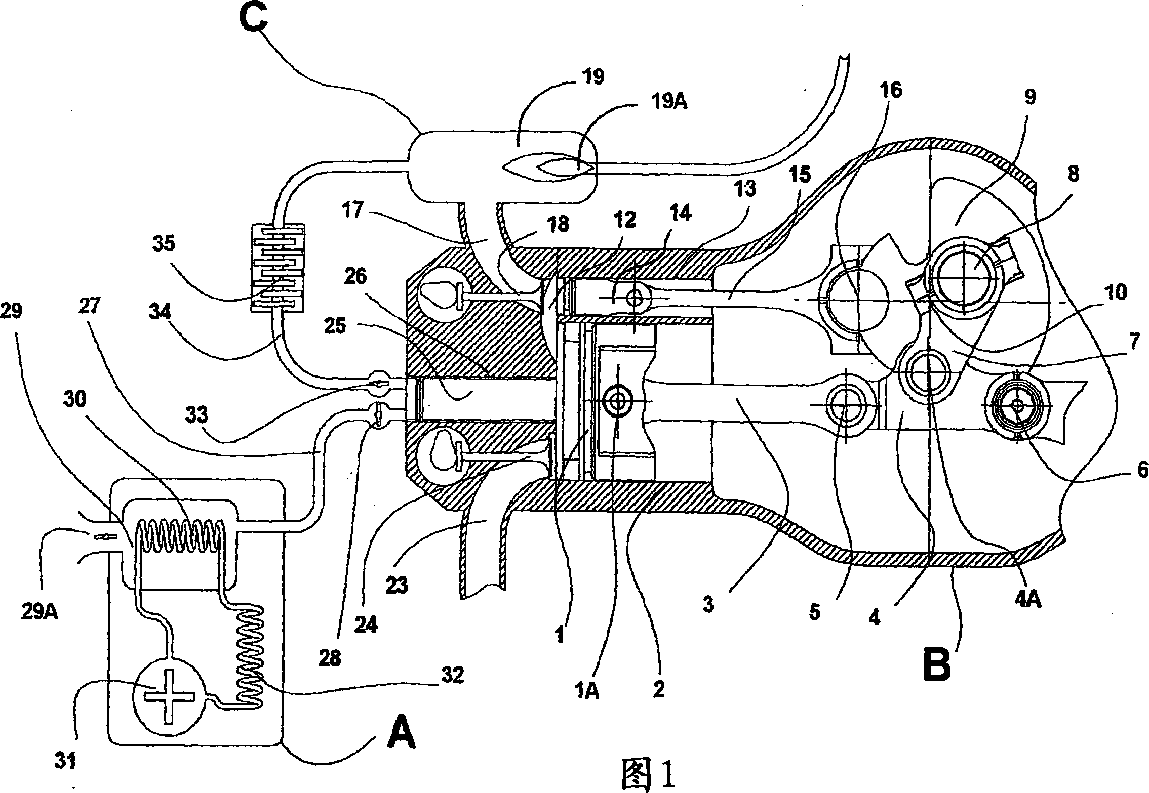
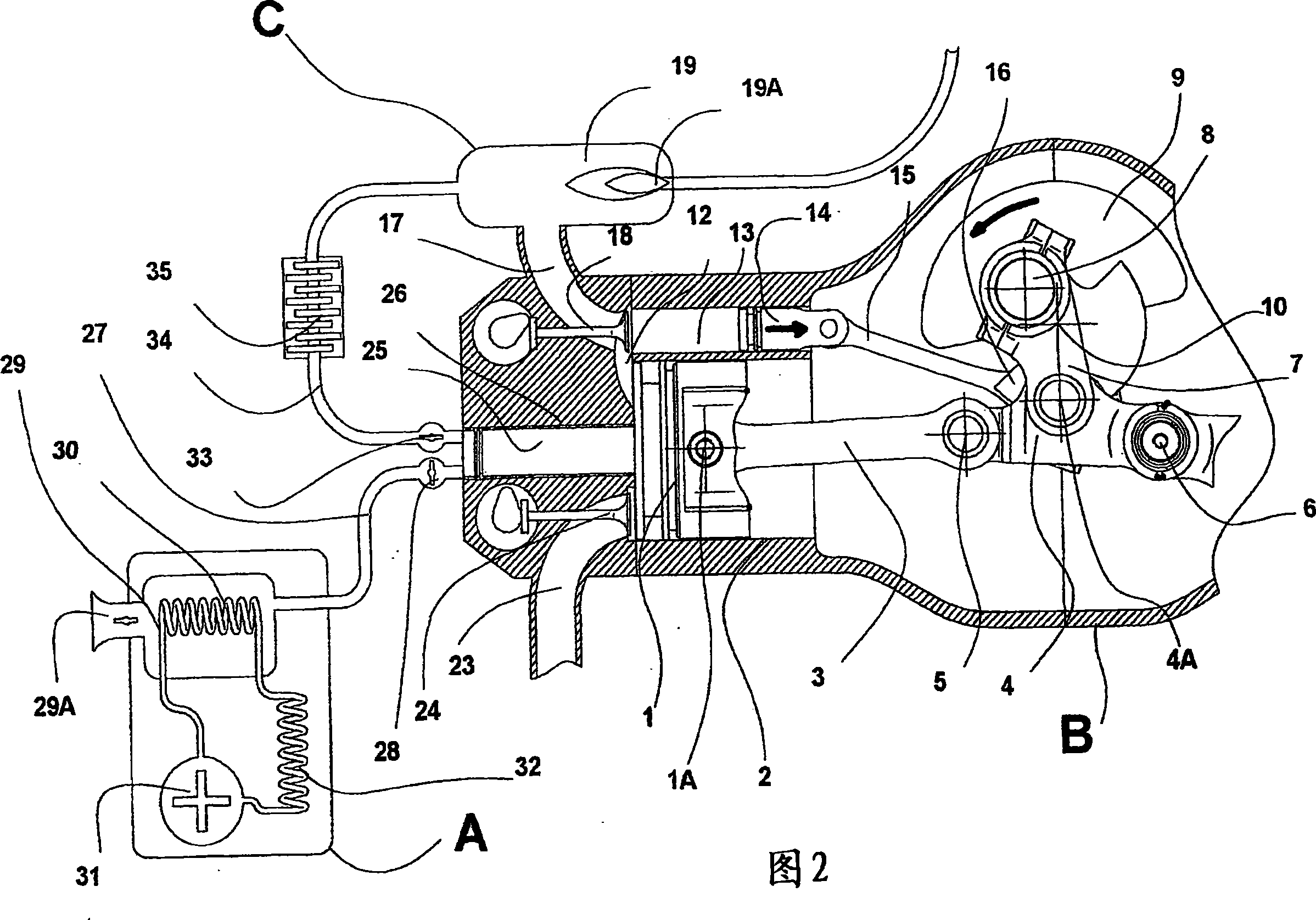
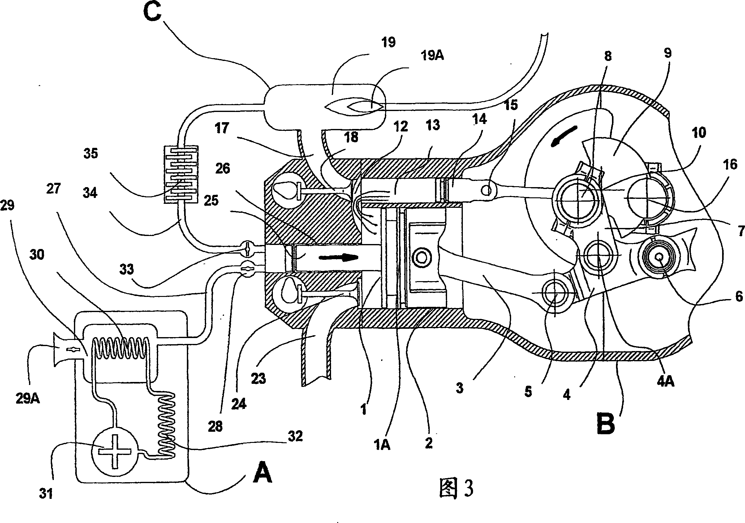
[0117] [117] Fig. 1 schematically shows in cross-section an active chamber cryogenic engine-compressor unit according to the invention, which has three main components: a cooling or refrigerating machine A, an engine-compressor unit B and an external combustion device C, Therein visible is the working piston 1 (shown at its top dead center) which slides in the cylinder 2 and is controlled by a pressure rod. The working piston 1 is connected via its shaft to the free end 1A of a pressure rod consisting of an arm 3 articulated on a common axis 5 to a further arm 4 , which is pivotally fixed on a fixed On the shaft 6, and the shaft 4A is basically arranged in the middle of the arm 4, and the control link 7 is connected to the shaft 4A, and the control link 7 is connected to the journal 8 of the crankshaft 9, and the crankshaft 9 Rotate on its axis 10. When the crankshaft rotates, the control connecting rod 7 exerts a force on the common shaft 5 of the two arms 3 and 4 of the pre...


PUM


Abstract

The invention relates to an active chamber type constant pressure continuous "cold" combustion type cryogenic engine-compressor unit, which works in particular with working compressed air and uses: a piston stroke control device and an active chamber with a cold chamber (29) which The atmosphere at the inlet (28) of the supply air compression device (28, 25, 26, 33) can be lowered to a very low temperature, which then compresses this working compressed air, which is still at low temperature, into the outer combustion chamber (19 ), the outer combustion chamber (19) is equipped with a constant pressure heating device (19A), and the working compressed air increases in volume in the heating device (19A), and then is transported quasi-isothermally to the active chamber ( 13), and then expand in the working cylinder (2) to do work again. The invention is applied to land vehicles, cars, buses, motorcycles, ships, airplanes, emergency power generation devices, household appliances, and stationary heat engines.

Description

technical field [0001] [01] The present invention relates to an engine-compressor unit, which operates in particular with compressed air, in particular: a piston stroke control device, whose function is to stop the piston at its top dead center and stop the engine for a period of time; to generate work variable volume active chamber; integrated (or non-integrated) compression device; and ambient heat recovery device, the unit can be operated with a single energy source of fuel or compressed air, or simultaneously or sequentially with fuel and compressed air Dual energy type operation. Background technique [0002] [02] This drafter has filed a number of patents dealing with mechanization and its equipment, working with compressed air, to be fully adapted for use in urban and suburban environments: [0003] [03] - WO 96 / 27737 WO 97 / 00655 WO 97 / 39232 [0004] [04] - WO 97 / 48884 WO 98 / 12062 WO 98 / 15440 [0005] [05] - WO 98 / 32963 WO 99 / 37885 [0006] [06] In order to use th...

Claims


Application Information

Patent Timeline
Patent Type & Authority Applications(China)
IPC IPC(8): F01B17/02F02B29/04
CPCF01B17/02F02B29/0462F02B29/0481F02G1/02F02G2250/03Y02E20/14Y02T10/12F02B29/04
Inventor G·内格尔C·内格尔
Owner MDI MOTOR DEV INT SA
Learn More