
Welding method and equipment

一种焊接方法、焊接设备的技术,应用在焊接设备、焊接设备、焊接/焊接/切割物品等方向,能够解决不良焊接、结构损伤、热量多等问题,达到提高质量、防止损伤、降低制造成本的效果

Active Publication Date: 2008-08-06
SAE MAGNETICS (HK) LTD
View PDF1 Cites 4 Cited by
  • Summary
  • Abstract
  • Description
  • Claims
  • Application Information

AI Technical Summary

Problems solved by technology

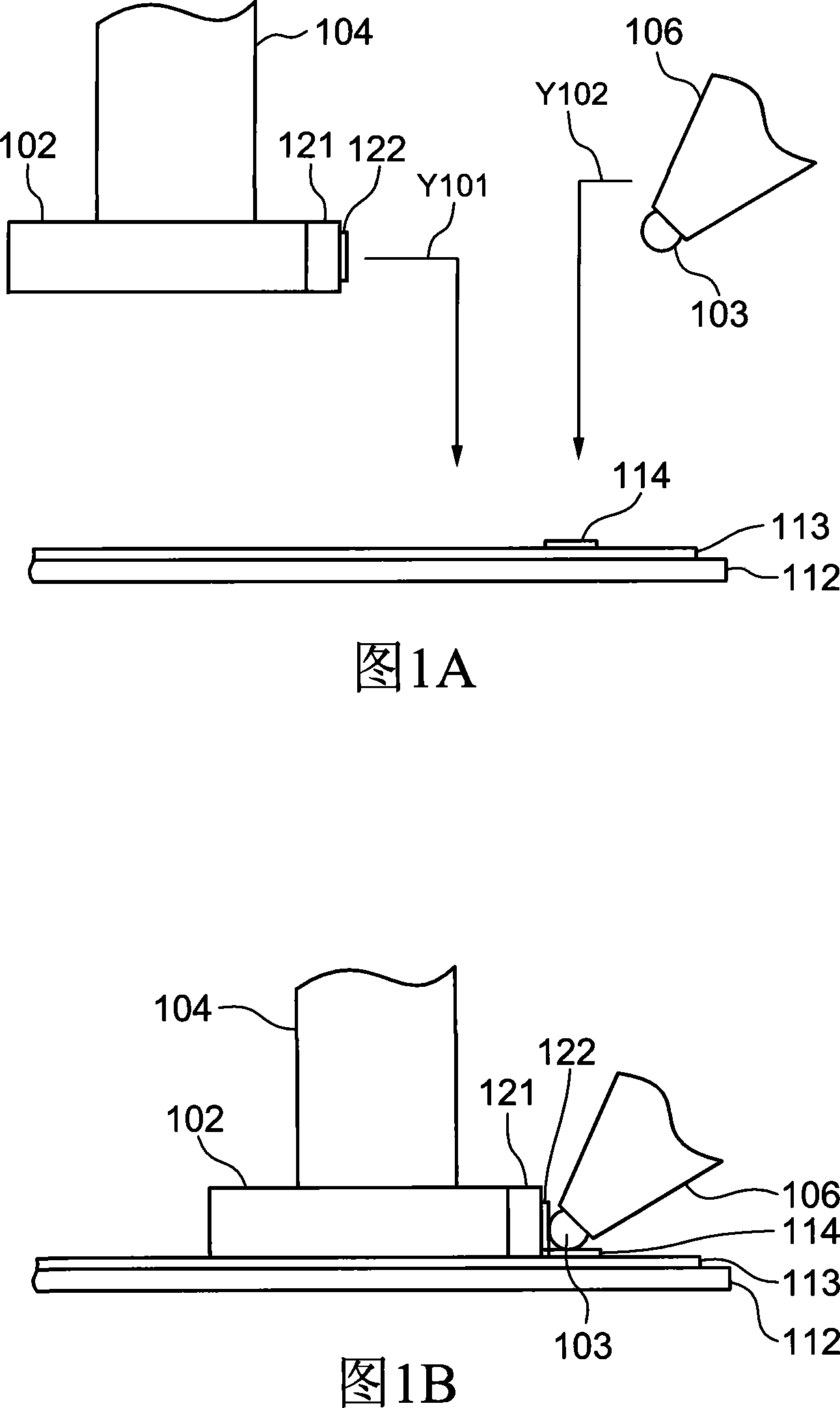
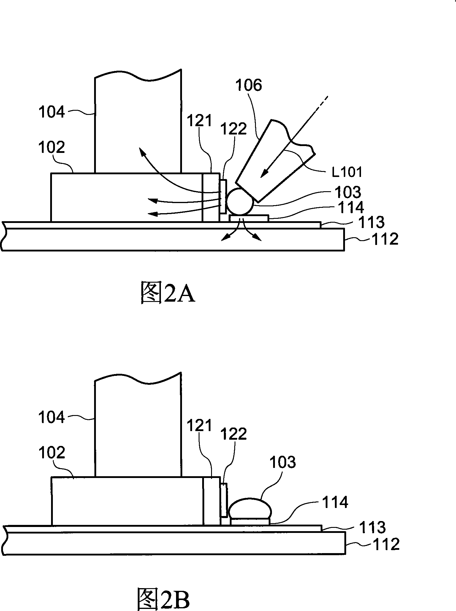
As a result, as shown in FIG. 2B , only the contact 114 on the side of the cantilever has a poor soldering phenomenon.
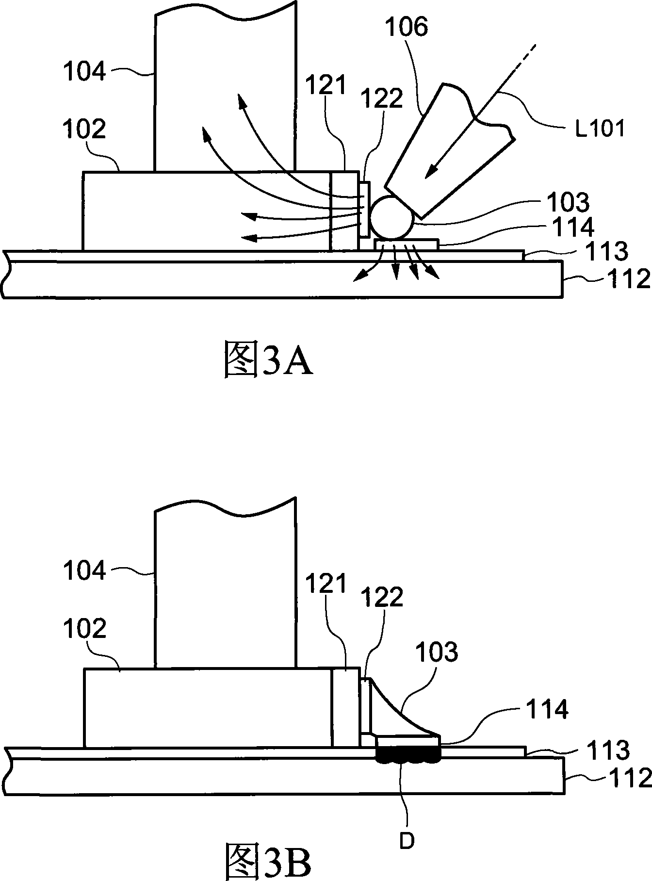
[0008] On the other hand, in order to avoid the above-mentioned bad soldering, the solder 103 is irradiated with a high-energy laser beam L101 (refer to FIG. 3A ) emitted by the laser irradiation nozzle 106 so that the slider side contact 122 with a low temperature can be heated to an appropriate temperature. Soldering can be achieved at a temperature above 100°C, however, too much heat will be applied to the cantilever side contact 114
Therefore, as shown in FIG. 3B, these excessive heats may cause damage to structures near the suspension side contacts 114 such as the polyimide layer (polyimide) forming the flexible printed circuit board.

Method used


Image

  • Welding method and equipment
  • Welding method and equipment
  • Welding method and equipment

Examples


no. 1 example

[0057] A first embodiment of the present invention will be described with reference to FIGS. 7 to 16 . FIG. 7 is a schematic structural diagram of a magnetic disk device, and FIG. 8 is a schematic structural diagram of a magnetic head gimbal assembly. 9 to 10 are structural schematic diagrams of the welding equipment, and FIG. 11 is a flow chart illustrating the steps of the welding method. 12 to 16 are explanatory diagrams showing welding states.

[0058] [structure]

[0059] Firstly, the welding equipment involved in this embodiment is used to manufacture the HGA 1 that can be carried on the magnetic disk device 100 as shown in FIG. 7 . Specifically, as shown in FIG. 8 , the soldering equipment can be used when connecting the head slider 2 to the flexible member 12 and the wire 13 that form the suspension member that can constitute the head gimbal assembly 1 . Here, the structure of the HGA 1 will be briefly described with reference to FIG. 8 .

[0060] The HGA 1 is prov...

no. 2 example

[0087] Next, a second embodiment of the present invention will be described with reference to FIGS. 17 to 22 . 17 to 18 are structural schematic diagrams of the welding equipment involved in this embodiment; FIG. 19 is a flowchart showing steps of the welding method; and FIGS. 20 to 22 are explanatory diagrams showing welding states.


PUM


Abstract

The present invention relates to a soldering method for bonding each of bonding pads formed in respective bonding targets with solder. The method comprises: a bonding target placing step for placing each of bonding targets to a bonding position; a soldering step for placing solder between each of the bonding pads formed in each of the bonding targets, and for performing soldering by irradiating a heating beam to the solder; and a bonding target heating step for heating at least one of the bonding targets, which is executed before the soldering step and / or simultaneously with the soldering step.

Description

technical field [0001] The invention relates to a welding method and welding equipment, in particular to a method and equipment for welding electronic components on an electronic circuit board. Background technique [0002] Soldering is a common method used to connect electronic components on substrates. Soldering can not only fix the electronic components on the substrate, but also electrically connect the terminals formed on the electronic components and the terminals formed on the substrate. For example, as described below, when manufacturing a head gimbal assembly (headgimbal assembly) carried on a magnetic disk device, a magnetic head as an electronic component can be welded on a suspension (suspension) integrally formed on a flexible printed circuit board slider. [0003] However, as mentioned above, when the connected body to be soldered is an electronic component, the heating during soldering will make the temperature of the electronic component higher than its hea...

Claims


Application Information

Patent Timeline
Patent Type & Authority Applications(China)
IPC IPC(8): B23K1/005B23K1/20B23K3/00B23K101/36B23K1/00B23K31/02G11B5/48H05K3/34
CPCH01L2224/742B23K1/0056H05K2203/041B23K2201/40H05K3/3494Y10T29/4903H05K2203/107H05K2201/10727H05K3/3442H01L2224/11003B23K2101/40Y02P70/50
Inventor 深谷浩山口哲
Owner SAE MAGNETICS (HK) LTD
Learn More