Oil decanting system for oil-sewage ship oil-sewage tank

A technology for oily sewage and decanting oil, which is applied in the direction of grease/oily substance/suspton removal device, liquid separation, separation method, etc., to achieve the effect of low investment, energy saving and stable work

Inactive Publication Date: 2008-08-06
DALIAN UNIV OF TECH
View PDF0 Cites 1 Cited by
  • Summary
  • Abstract
  • Description
  • Claims
  • Application Information

AI Technical Summary

Problems solved by technology

For the floating oil and dispersed oil in the land sewage plant, through the long-term oil separation and sedimentation in the oily sewage tank, the floating oil is usually driven into the sewage pool by manual operation, and the oily sewage tank of the oily sewage ship is closed and explosion-proof Yes, there is no ready-made decanter product available

Method used


Image

  • Oil decanting system for oil-sewage ship oil-sewage tank
  • Oil decanting system for oil-sewage ship oil-sewage tank

Examples


Embodiment Construction

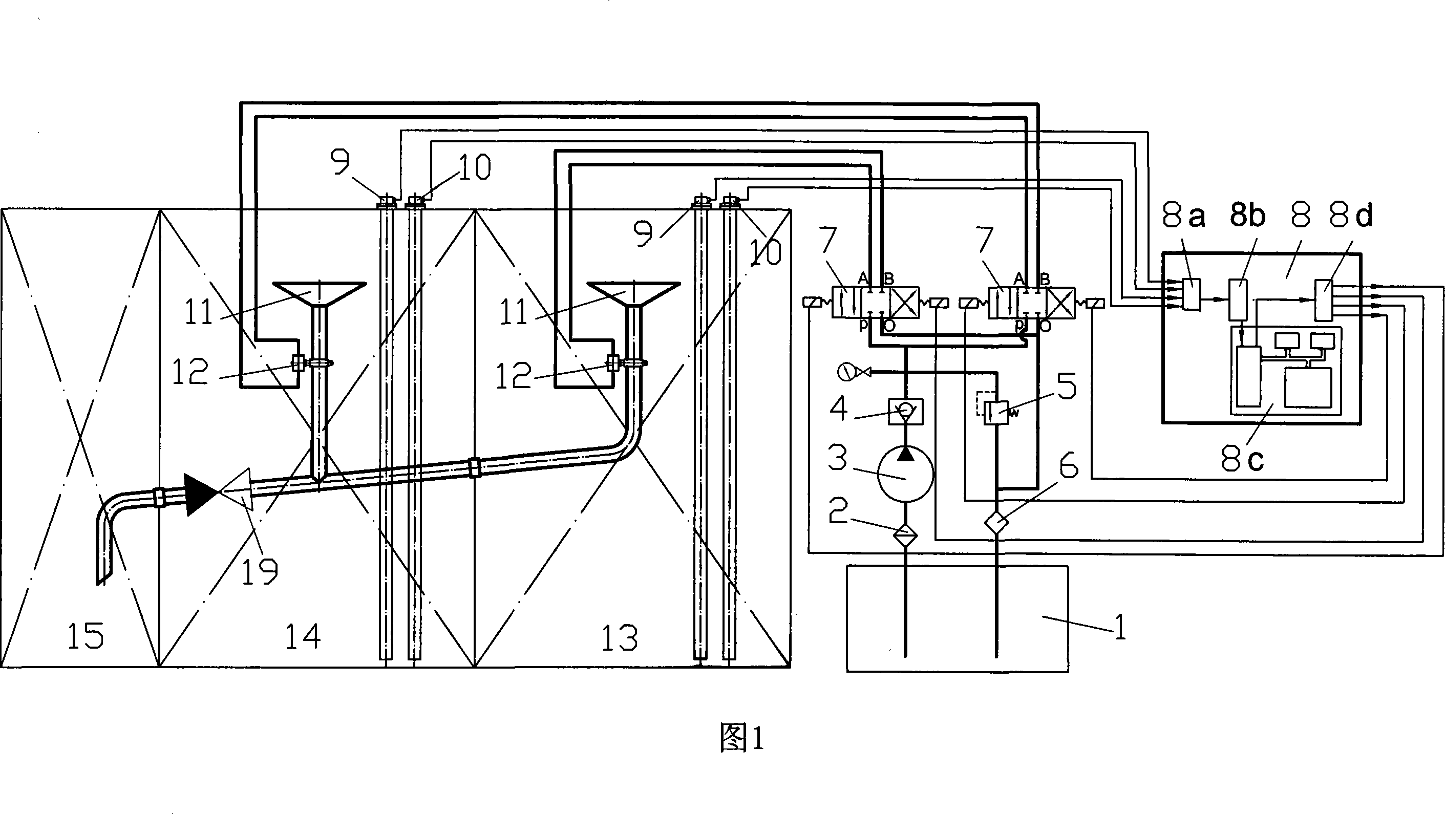
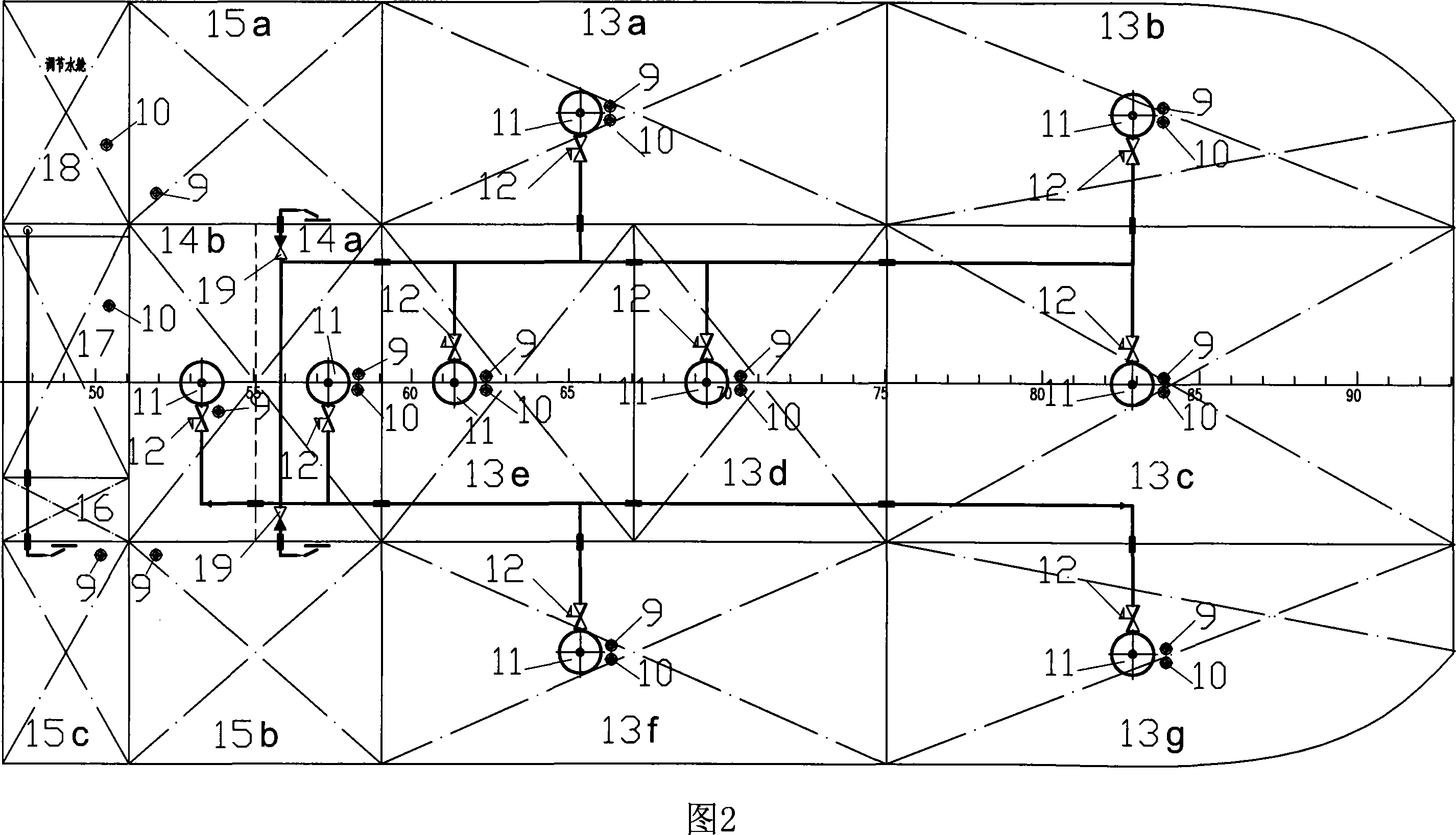
[0013] In order to gain an in-depth understanding of the decanting system of the oily slop tank of the oily slop tank, the description is as follows in conjunction with Figures 1 and 2:

[0014] Figure 1 shows the schematic diagram of the oil decanting system in the oily sewage tank. In the figure, the hydraulic pump 3 absorbs oil from the hydraulic oil tank 1 through the filter 2, supplies the hydraulic oil to the three-position four-way solenoid valve 7 through the check valve 4, and a part of the hydraulic oil returns to the hydraulic oil tank through the overflow valve 5 and the cooler 6 1. Generally, there are two sets of hydraulic pumps 3, one of which is a spare, and the working pressure of the hydraulic oil is 5.3-6 MPa. An oil decanting funnel 11 is set in the middle of the oily sewage tank 13 and the sloping plate oil separation tank 14. The lower part of the oil decanting funnel 11 is connected to a hydraulic remote control valve 12 through a pipeline, and the lowe...


PUM

PropertyMeasurementUnit
particle diameteraaaaaaaaaa

Abstract

The invention relates to an oil decanting system for an oil stain boasting and an oil water chamber, which belongs to the field of vessel sewage treatment and environment protection. The oil decanting system of the oil stain boasting and the oil water chamber adopts a hydraulic device and each hydraulic remote value is provided with a tee and double-position electromagnetic valve. The electronic unit controls the tee and double-position electromagnetic valve according to a set parameter in a storage device based on the input signal of an oil-water interface meter and a liquid level meter. When the tee and double-position electromagnetic valve opens the corresponding hydraulic control value, the polluted oil in the hydraulic oil floating on the surface of the oil stain water chamber flows to the oil stain chamber through an oil decanting filter. The oil decanting system has the advantages of low investment, energy saving, stable operation with safety and reliability, as well as a high automatic degree and convenient maintenance and management.

Description

technical field [0001] The invention relates to an oil decanting system for an oily sewage tank of an oily sewage ship, which belongs to the fields of ship sewage treatment and environmental protection. Background technique [0002] Different forms of oil in oily wastewater have different physical and chemical properties, which largely determine the choice of treatment methods. Generally, oil exists in five forms in water: (1) The particle size of floating oil particles is larger than 50 microns, which can quickly float to the water surface and form an oil film after standing still. (2) The oil particle diameter of dispersed oil is small, generally tens of microns, suspended and dispersed in water, but unstable, and can be aggregated into larger oil droplets to float to the water surface. (3) The particle size of the emulsified oil is generally below 10 microns. Due to the use of surfactants or mechanical action, the oil is emulsified with water to form a stable emulsion, w...

Claims


Application Information

Patent Timeline
Patent Type & Authority Applications(China)
IPC IPC(8): C02F1/40
Inventor 马坤林焰张明霞金朝光吴俊杰李树立纪卓尚王运龙于雁云
Owner DALIAN UNIV OF TECH
Why Eureka
Try Eureka