Stepless speed variator

A technology of continuously variable transmission and coupling, which is applied in the direction of gear transmission, fluid transmission, belt/chain/gear, etc., can solve the problems of complex structure, low power and low efficiency of continuously variable transmission, and achieve simple structure, High average speed, easy maintenance effect

Inactive Publication Date: 2008-08-06
吴志强
0 Cites 32 Cited by

AI-Extracted Technical Summary

Problems solved by technology

[0002] At present, the commonly used continuously variable transmissions are designed according to the principles of friction and hydrostatics, etc., and the power they can transmit is not large, and the efficiency ...

Abstract

The invention provides a stepless transmission, which aims at providing a stepless transmission which prolongs the service life of the motor and the actuating system, has simple structure, convenient operation, low cost and is energy saving and highly efficient. The main points of the technical scheme is that the invention includes an input shaft, a coupler, a one-way clutch, a neutral and reverse mechanism and an output shaft, wherein an output end 52 of the one-way clutch 5 is connected with the output shaft 1, an output end 72 of the neutral and reverse mechanism 7 is connected with an output shaft 8, a moment converting unit 2 composed of a planetary row 3 and a public output shaft 6 which are sequentially collected and an one-way element 9 is arranged between the output shaft 1 and the output shaft 8, an input end of the moment converting unit 2 is connected with an input shaft 1, an output end 22 is connected with a coupler 4, an output end 44 of the coupler is connected with a plurality of elements except for elements of the stepless transmission, one end of a public output end 23 of the moment converting unit 2 is connected with an input end 71 of the neutral and reverse mechanism 7, and the other end is connected with an input end 51 of the one-way clutch 5.

Application Domain

Technology Topic

Image

  • Stepless speed variator
  • Stepless speed variator
  • Stepless speed variator

Examples

  • Experimental program(6)

Example Embodiment

[0028] Embodiment one:
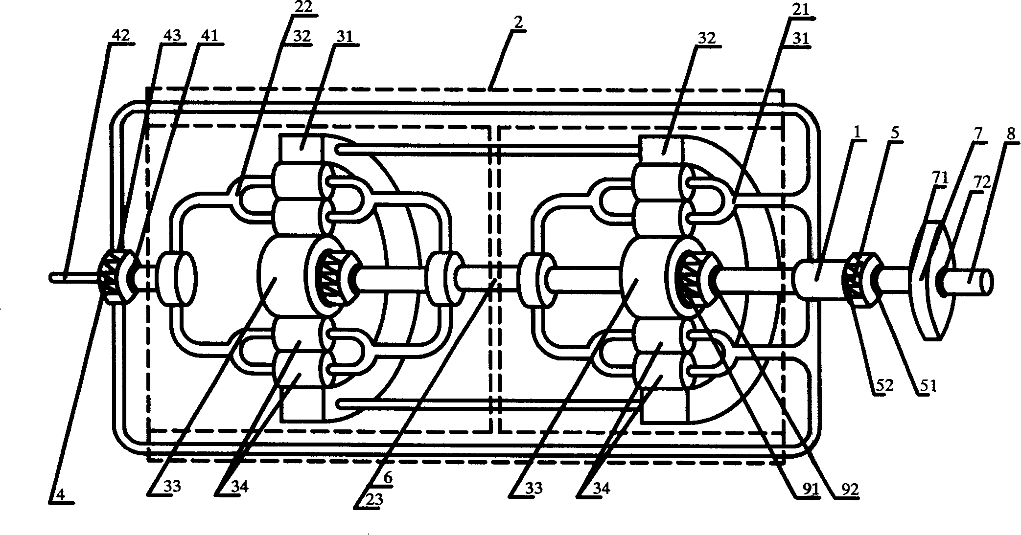
[0029] like figure 1 As shown in , a continuously variable transmission includes an input shaft 1, a coupling 4, a one-way clutch 5, an empty and reverse gear mechanism 7, and an output shaft 8. The output end 52 of the one-way clutch 5 is connected to the input shaft 1 Connection, the output end 72 of the neutral and reverse gear mechanism 7 is connected with the output shaft 8, and there is a planetary row 3 connected in sequence between the input shaft 1 and the output shaft 8, a common output shaft 6 and a one-way The torque conversion unit 2 composed of elements 9, the planetary row 3 includes an input element 31, an output element 32, a common output element 33, and a planetary gear 34, the input element 31 of the first planetary row 3 is connected with the input shaft 1, and the second The input element 31 of the first planetary row 3 is connected with the output element 32 of the first planetary row 3, the output element 32 of the second planetary row 3 is connected with the input end 41 of the coupler 4, and the output end 42 of the coupler 4 is connected with the present invention The common output end 43 of the coupler 4 is connected with the input element 31 of the first planetary row 3, and the common output element 33 of the two planetary rows 3 is connected with the input end 91 of the corresponding one-way element 9 respectively. , the output ends 92 of the two one-way elements 9 are respectively connected with the common output shaft 6, one end of the common output shaft 6 is connected with the input end 71 of the neutral and reverse gear mechanism 7, and the other end is connected with the input end 51 of the one-way clutch 5 connect.
[0030] Described coupler 4, one-way element 9 select one-way clutch for use.
[0031] The input power is divided into two paths by the input element 31 of the first planetary row 3 of the torque converter unit 2, one path flows into its common output element 33, and the other path flows through its output element 32 into the input element 31 of the second planetary row 3 , and repeat the above-mentioned shunting process in this planetary row 3.
[0032]Since the component rotation speed distribution relationship between each planetary row 3 can be changed, the two power flows will change according to the change in the rotation speed distribution between the two. When the rotation speed of the common output component 33 is zero, its input power is zero, but the torque is not zero, at this time, the input power of the output elements 32 of each planetary row 3 is changed from a certain value to the maximum value, and the certain value refers to when the output elements 32 of each planetary row 3 are connected to the respective common output elements When the rotational speed of 33 is the same, the value obtained by distributing the input power according to the torque ratio of the planetary row, the maximum value refers to the total power input by the engine or the output element 32 of the last planetary row 3 respectively, that is to say, When the two-way power changes, the output element 32 of each planetary row 3 will change the torque or change the power, so that the torque transmitted to the next planetary row 3 or coupling 4 is divided and then transmitted to the respective The torque of the common output element 33 of the first planetary row 3 or the input element 31 of the first planetary row 3 also changes accordingly, that is to say, the torque on the output shaft 8 also changes accordingly.
[0033] The input power of the engine is split into two paths through the input element 31 of the first planetary row 3, one path flows into its common output element 33, and the other path flows into the input element 31 of the second planetary row 3 through its output element 32. Then split into two paths, and repeat the above-mentioned splitting process, finally, the power transmitted to the output element 32 of the second planetary row 3 is then transmitted to the input end 41 of the coupling 4, and then split into two paths, one path passes through the coupling The output end 42 of 4 flows into some elements other than the present invention, and the input element 31 of the input element 31 that another road flows into the first planetary row 3 through the common output end 4 of coupler 4 and the confluence of the input power of engine, and repeats above-mentioned shunting process, and respectively The power flowing into the common output elements 33 of the two planetary rows 3 flows into the common output shaft 6 through the one-way element 9 matched with it respectively, and the common output shaft 6 flows into the output shaft 8 of the present invention through the empty and reverse gear mechanism 7 again , thereby realizing the external output of the power of the engine through the output shaft 8 .

Example Embodiment

[0034] Embodiment two:
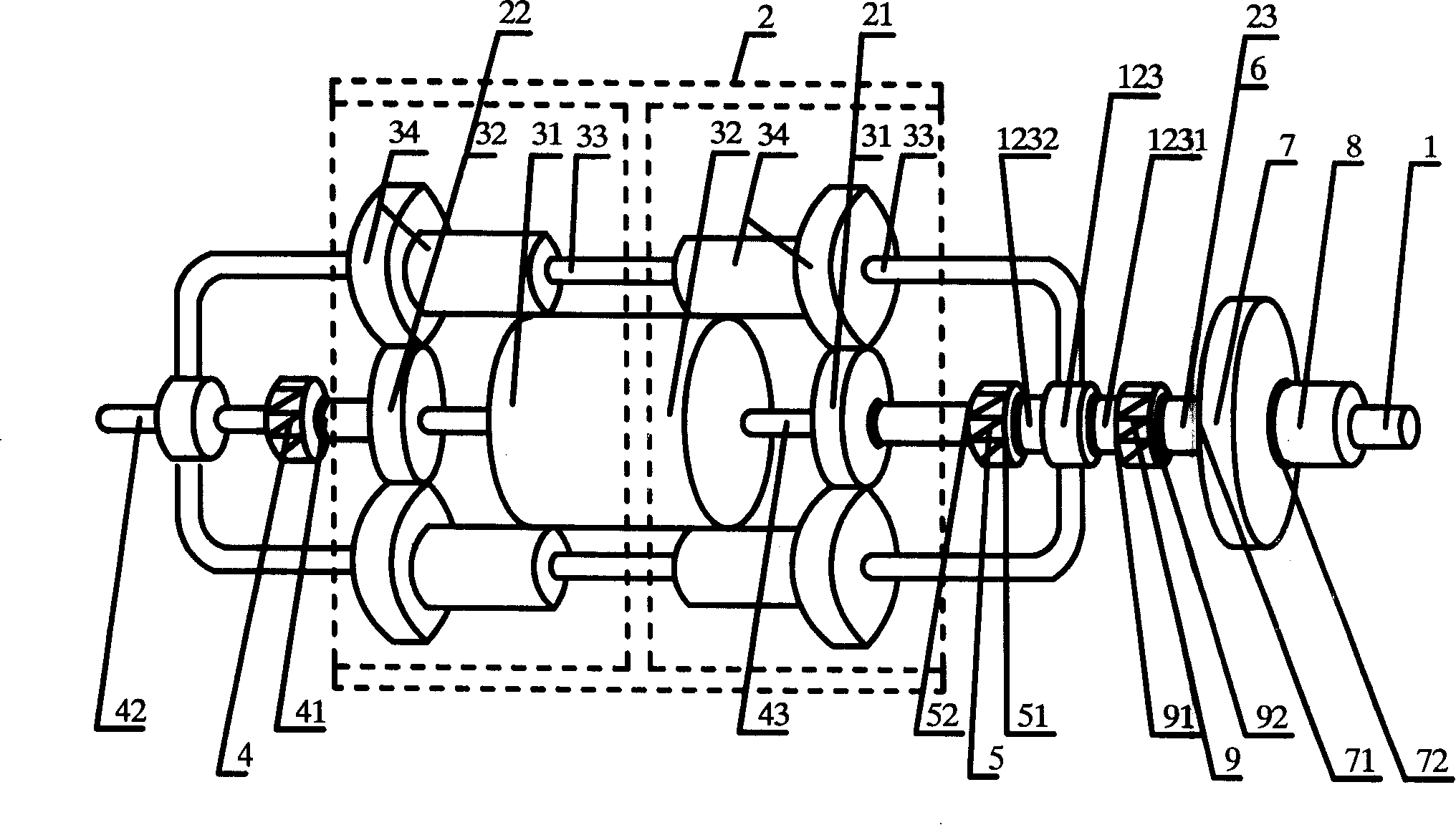
[0035] like figure 2 As shown in , it includes input shaft 1, coupling 4, one-way clutch 5, neutral and reverse gear mechanism 7, output shaft 8, the output end 52 of said one-way clutch 5 is connected with input shaft 1, neutral and reverse gear The output end 72 of the mechanism 7 is connected to the output shaft 8, and there is a torque converter composed of two sequentially connected planetary rows 3, a common output shaft 6 and a one-way element 9 between the input shaft 1 and the output shaft 8. Unit 2, the planetary row 3 includes an input element 31, an output element 32, a common output element 33, and a planetary gear 34. The input element 31 of the first planetary row 3 is connected to the input shaft 1, and the input of the second planetary row 3 The element 31 is connected with the output element 32 of the first planetary row 3, the output element 32 of the second planetary row 3 is connected with the input end 41 of the coupler 4, and the output end 42 of the coupler 4 is connected with several elements outside the present invention, The common output end 43 of the coupler 4 is connected with the input element 31 of the first planetary row 3, and the common output element 33 of the two planetary rows 3 is the same element, that is, a common output element 123, which is connected with the input end of the one-way element 9. 91 connection, the output end 92 of the one-way element 9 is connected with the common output shaft 6, one end of the common output shaft 6 is connected with the input end 71 of the neutral and reverse gear mechanism 7, and the other end is connected with the input end 51 of the one-way clutch 5 .
[0036] Described coupler 4, one-way element 9 select one-way clutch for use.
[0037] Among them, the difference between this embodiment and the first embodiment is that the common output element 33 of the two planetary rows 3 is the same element, that is, the common output element 123 is shared, thereby reducing one unidirectional element 9 .
[0038] The input power is split into two paths by the input element 31 of the first planetary row 3 of the torque converter unit 2, and one path flows into its common output element 33, that is, a common common output element 123, and the other path flows into the second through its output element 32. input element 31 of the planetary row 3, and repeat the above-mentioned flow splitting process in this planetary row 3.
[0039] Since the component rotation speed distribution relationship between each planetary row 3 can be changed, the two power flows will change according to the change in the rotation speed distribution between the two. When the rotation speed of the shared common output component 123 is zero, its input power is zero. But the torque is not zero. At this time, the input power of the output elements 32 of each planetary row 3 is changed from a certain value to a maximum value. When the rotational speed of the output element 33 is the same, the value obtained by distributing the input power according to the torque ratio of the planetary row, the maximum value refers to the total power input by the engine or the output element 32 of the last planetary row 3 respectively, that is That is to say, when the two-way power changes, the output element 32 of each planetary row 3 will change the torque or change the power, so that the torque transmitted to the next planetary row 3 or coupling 4 is divided and then transmitted The torque to the common common output element 123 or to the input element 31 of the first planetary row 3 also changes accordingly, that is to say the torque on the output shaft 8 also changes accordingly.
[0040] The input power of the engine is split into two paths through the input element 31 of the first planetary row 3, one path flows into the common output element 123, and the other path flows into the input element 31 of the second planetary row 3 through its output element 32, and this power is then The flow is split into two paths, and the above-mentioned splitting process is repeated. Finally, the power transmitted to the output element 32 of the second planetary row 3 is then transmitted to the input end 41 of the coupling 4, and then split into two paths, and one path passes through the power of the coupling 4. The output end 42 flows into some components other than the present invention, and the input element 31 of the other way flows into the input element 31 of the first planetary row 3 and the input power confluence of the engine through the common output end 43 of the coupler 4, and repeats the above-mentioned shunting process, and flows into two respectively. The power of the shared public output element 123 of each planet row 3 flows into the common output shaft 6 through the one-way element 9, and the common output shaft 6 flows into the output shaft 8 of the present invention through the neutral and reverse gear mechanism 7, thereby realizing the engine The power is output externally through the output shaft 8.

Example Embodiment

[0041] Embodiment three:
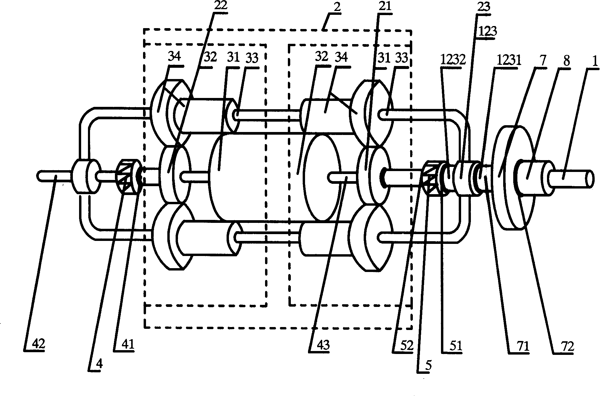
[0042] like image 3 As shown in the present embodiment, only one end 1231 of the common output element 123 of the two planetary rows 3 in the second embodiment is directly connected to the input end 71 of the neutral and reverse gear mechanism 7, thereby reducing the number of one-way elements 9 and The common output shaft 6, its working principle and realized functions and effects remain unchanged.

PUM

no PUM

Description & Claims & Application Information

We can also present the details of the Description, Claims and Application information to help users get a comprehensive understanding of the technical details of the patent, such as background art, summary of invention, brief description of drawings, description of embodiments, and other original content. On the other hand, users can also determine the specific scope of protection of the technology through the list of claims; as well as understand the changes in the life cycle of the technology with the presentation of the patent timeline. Login to view more.

Similar technology patents

Classification and recommendation of technical efficacy words

  • Simple structure
  • Low manufacturing cost

Microlithographic projection exposure apparatus

InactiveUS20050068499A1Simple structureReliable and low-maintenance operationProjectorsPhotomechanical exposure apparatusCamera lensPhysics
Owner:CARL ZEISS SMT GMBH

Exercise equipment

InactiveUS6942605B1Low manufacturing costLow price of saleStraight-bar knitting machinesFootwearExercise equipmentPhysical medicine and rehabilitation
Owner:SUKHOVITSKY FELIKS

Hybrid aerial and terrestrial vehicle

ActiveUS20140131507A1Simple designLow manufacturing costConvertible aircraftsMicro-sized aircraftFlight vehicleTerrestrial locomotion
Owner:ILLINOIS INSTITUTE OF TECHNOLOGY

A ceramic insulator device for high voltage capacitor

InactiveCN101546636ALow manufacturing costReasonable structureSuspension/strain insulatorsHigh voltage capacitorsEngineering
Owner:王海龙
Why Eureka
Try Eureka