Clock production circuit structure and production method

A clock generation circuit and clock signal technology, applied in the direction of generating electrical pulses, pulse generation, electrical components, etc., can solve problems such as time-consuming and user inconvenience, and achieve the effect of avoiding abnormality

Active Publication Date: 2008-08-06
HOLTEK SEMICON
View PDF0 Cites 4 Cited by
  • Summary
  • Abstract
  • Description
  • Claims
  • Application Information

AI Technical Summary

Problems solved by technology

In this way, the user also spends a lot of time waiting for the normal operation of the liquid crystal display, thereby causing inconvenience to the user.

Method used


Image

  • Clock production circuit structure and production method
  • Clock production circuit structure and production method
  • Clock production circuit structure and production method

Examples


Embodiment Construction

[0044] In order to have a further understanding of the purpose, structure, features, and functions of the present invention, a detailed description is now provided in conjunction with the embodiments.

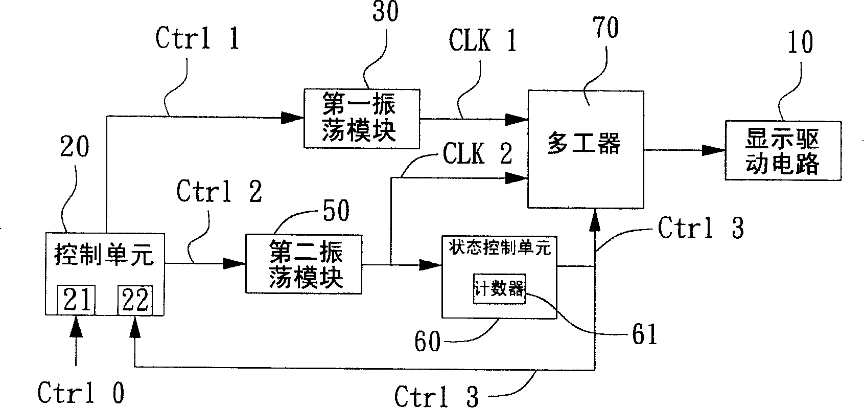
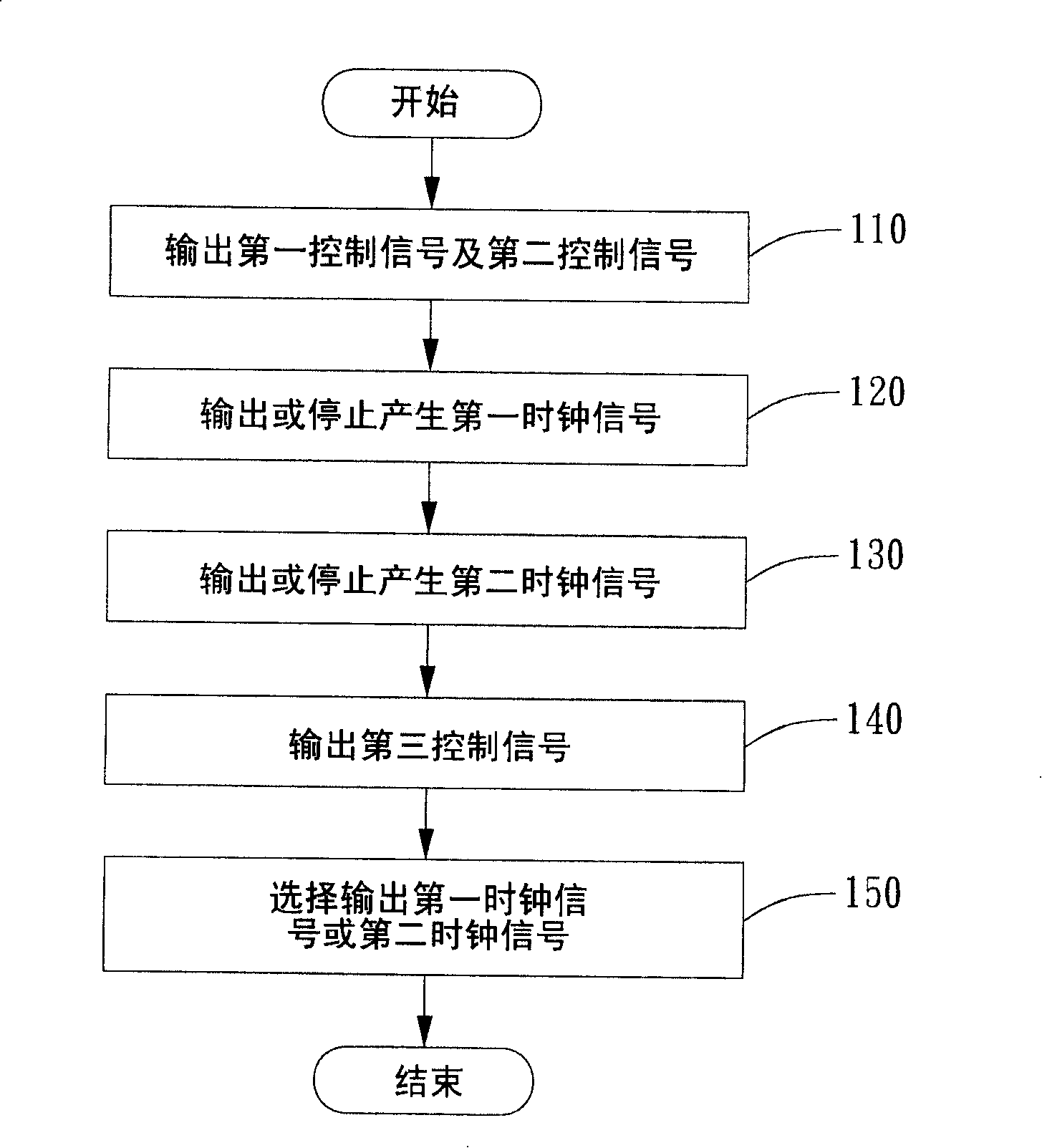
[0045] figure 2 It is a block diagram of an embodiment of a clock generation circuit structure of the present invention. This embodiment includes a control unit 20, a first oscillation module 30, a second oscillation module 50, a state control unit 60, and a multiplexer 70, and is applied to a liquid crystal display, but is not limited to the liquid crystal display. image 3 It is a flowchart of an embodiment of a clock generation method of the present invention. The present embodiment includes the following steps: outputting a first control signal and a second control signal (step 110). Output or stop generating the first clock signal (step 120). Output or stop generating the second clock signal (step 130). The third control signal is output (step 140). Select whether to output ...


PUM


Abstract

The invention relates to a clock generating circuit structure and a generating method, wherein, the structure comprises a control unit, a first oscillating module, a second oscillating module, a state control unit and a multiplexer. The control unit outputs a first control signal and a second control signal to stop the first oscillating module and the second oscillating module or generate a first clock signal and a second clock signal to the multiplexer. The state control unit is used for judging whether the second clock signal reaches a stable state and controlling the multiplexer to selectively output the first clock signal or the second clock signal in order to keep a clock output by the multiplexer in the stable state. With the invention, a liquid crystal display can immediately acquire a normal working clock from a standby mode to an operation mode; therefore, the speed during the period from starting oscillation to reaching the stable state by the clock is fast; a stable clock is provided through the first oscillating module and the second oscillating module, thereby avoiding the picture of the liquid crystal display from producing abnormal phenomena.

Description

Technical field [0001] The invention relates to a clock generating circuit structure and a generating method, and more particularly to a clock generating circuit structure and a generating method applied to a liquid crystal display. Background technique [0002] When the LCD monitor is in HALT mode, sleep mode, power down mode, or standby mode, etc., the LCD monitor is in a low power consumption operating mode, which is based on power saving. Electricity demand, except that the basic functions and monitoring actions of the display driver chip or microcontroller are still maintained, so that they have the ability to identify the control functions required by the external control system, other circuits with non-basic functions are suspended to save electricity. [0003] See figure 1 As shown, it is a block diagram of a clock generating circuit and a display driving circuit of a conventional liquid crystal display. The structure of the traditional clock generating circuit includes ...

Claims


Application Information

Patent Timeline
Patent Type & Authority Applications(China)
IPC IPC(8): H03K5/15H03K3/014
Inventor 余国成陆庭元
Owner HOLTEK SEMICON
Why Eureka
Try Eureka