Frame synchronization device and method for T-DMB system receiver

A T-DMB and receiver technology, applied in the field of T-DMB system receiver frame synchronization, can solve problems such as large amount of calculation, difficult threshold value, and large storage resources, so as to overcome the interference of time domain pulses and reduce the Hardware implementation overhead, the effect of reducing storage resources

Active Publication Date: 2008-08-13
MAXSCEND MICROELECTRONICS CO LTD
View PDF0 Cites 6 Cited by
  • Summary
  • Abstract
  • Description
  • Claims
  • Application Information

AI Technical Summary

Problems solved by technology

[0006] Therefore, in the current T-DMB frame synchronization technology, it can be roughly divided into two types. One is to use PRS symbols for synchronization, that is, to perform sliding correlation on the received signal to find the correlation peak. The advantage of this method is that it uses correlation gain. It can effectively resist signal fading and improve the detection success rate, but the calculation amount is relatively large and consumes a lot of resources
Another relatively simple method is to detect the null symbol, and find the boundary of the null symbol through the set threshold value. This method usually needs to perform low-pass filtering on the signal, and then detect the filtered waveform, but a suitable gate It is difficult to choose the limit value. In different channel environments, different threshold values ​​need to be replaced. On the other hand, if you want to resist the random fading of the signal, you need to increase the order of the low-pass filter, so the storage resources consumed are also grow bigger

Method used


Image

  • Frame synchronization device and method for T-DMB system receiver
  • Frame synchronization device and method for T-DMB system receiver
  • Frame synchronization device and method for T-DMB system receiver

Examples


Embodiment Construction

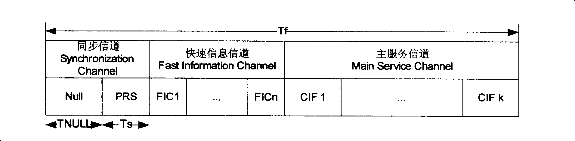
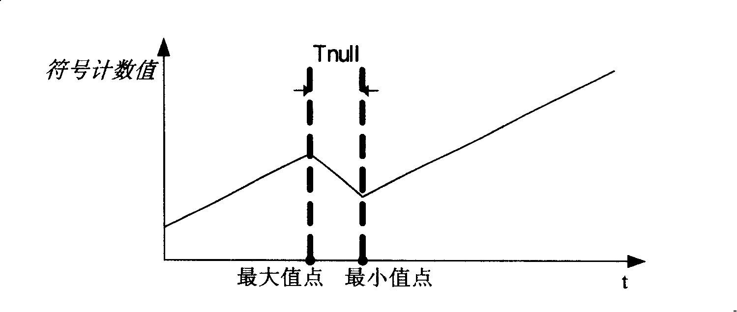
[0023] For the null symbol of the synchronous channel, although the signal at the sending end is 0, there is still relatively large noise after passing through the channel interference; therefore, the simple threshold value setting often fails in the detection, in order to detect the null symbol , the present invention introduces a symbol counter. The basic idea is to find the difference between the signal amplitude M and the fixed threshold T, and count the sign bit S of the difference. In non-null symbols, S should be mostly 1, and in null symbols, S is -1, so the count value of this symbol counter will have a change trend similar to that of a zigzag (its shape can be referred to figure 2 ), as long as the two turning points of the count value change are determined, the starting point and the ending point of the null symbol are found, thereby determining the position of the frame header.

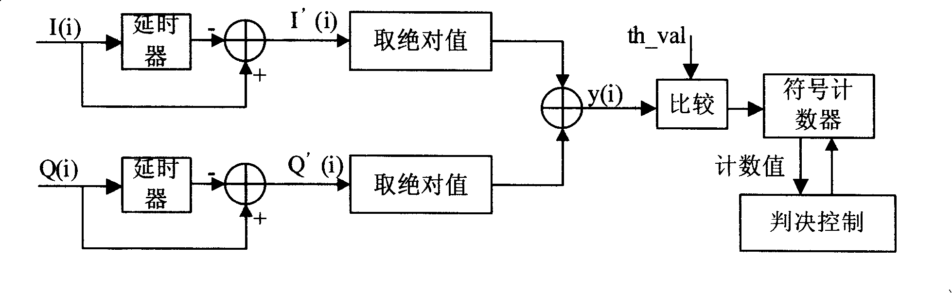
[0024] The synchronization process that the present invention specifically realizes ...


PUM


Abstract

The present invention provides a frame synchronizer of T-DMB system receiver and its method, the device includes adder 1, selftimer 1, adder 2, selftimer 2. adder 3, a comparator, a sign counter and a decision control state machine, wherein the adders 1, 2, the selftimers 1, 2 are used for receiving input signal and the sending in the adder 3 after dot difference; the adder 3 sends the processing result to the comparator and then sends to the sign counter, the sign counter sends the enumerated data to the decision control state machine and receives the feedback of the decision control state machine. The frame synchronizer processes counting by receiving the signl of the signal width and the difference of threshold, and judging null interval, the method is quick and high effect, only using some control state machines and simple adding unit can realize because of having no filter, the method reduces the spending of the hardware, effectively overcomes time pulse.

Description

technical field [0001] The invention relates to a frame synchronization device in a T-DMB standard digital television broadcasting receiving system; the invention also relates to a frame synchronization method of a T-DMB system receiver. Background technique [0002] T-DMB is a terrestrial digital multimedia broadcasting standard launched by South Korea. This standard is based on the European digital broadcasting standard DAB with some modifications, in order to transmit wireless digital TV programs to handheld devices such as mobile phones, PDAs and portable TVs. [0003] The transmission frame structure of T-DMB digital TV standard is as follows: figure 1 As shown, each frame is divided into three parts: a synchronization channel (Synchronization Channel), a fast information channel (Fast Information Channel) and a main service channel (Main Service Channel). The synchronization channel is located at the beginning of each frame, occupies two symbol lengths, and plays the ...

Claims


Application Information

Patent Timeline
Patent Type & Authority Applications(China)
IPC IPC(8): H04N7/54H04N7/52H04L7/00
Inventor 蒋朱成吴涛张帆冯晨晖周立丰
Owner MAXSCEND MICROELECTRONICS CO LTD
Why Eureka
Try Eureka