Apparatus and methods for spectrum based monitoring of chemical mechanical polishing

A spectrum, grinding pad technology, used in grinding devices, grinding machine tools, grinding tools, etc., to achieve the effect of improving accuracy

Inactive Publication Date: 2008-08-13
APPLIED MATERIALS INC
View PDF5 Cites 27 Cited by
  • Summary
  • Abstract
  • Description
  • Claims
  • Application Information

AI Technical Summary

Problems solved by technology

Therefore, the end point of grinding cannot be judged only as a function of grinding time

Method used


Image

  • Apparatus and methods for spectrum based monitoring of chemical mechanical polishing
  • Apparatus and methods for spectrum based monitoring of chemical mechanical polishing
  • Apparatus and methods for spectrum based monitoring of chemical mechanical polishing

Examples


Embodiment Construction

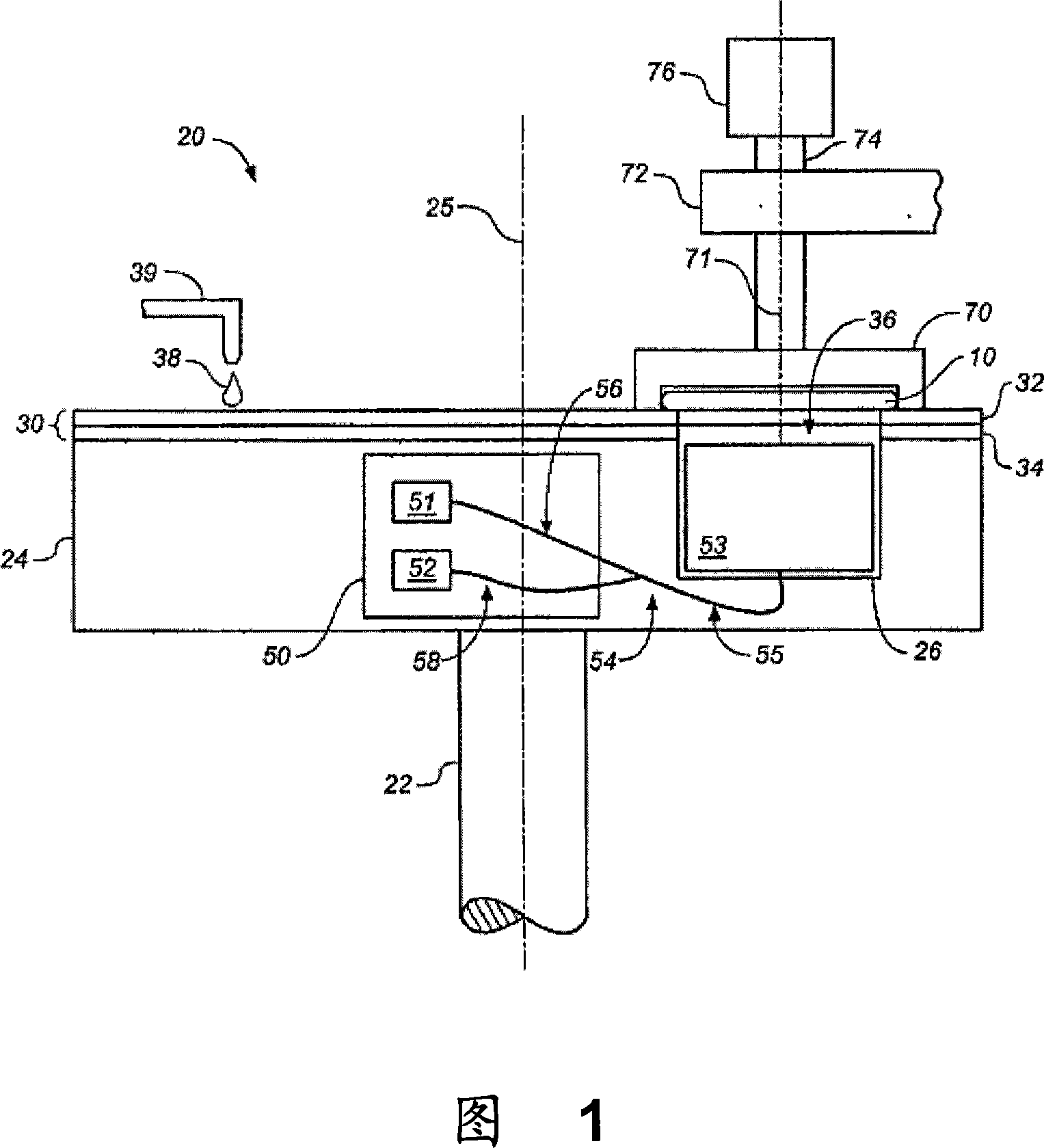
[0073] FIG. 1 illustrates a grinding apparatus 20 that may be used to grind a substrate 10 . The grinding device 20 includes a rotatable disc platform 24 on which a grinding pad 30 is disposed. The platform is rotatable about axis 25 . For example, a motor can turn a drive rod 22 to rotate the platform 24 . The polishing pad 30 can be removably secured to the platform 24, for example, with a layer of adhesive. When exhausted, the abrasive pad 30 can be removed and replaced. The polishing pad 30 may be a two-layer polishing pad having an outer abrasive layer 32 and a softer back abrasive layer 34 .

[0074] Optical access 36 through the polishing pad is provided by including a hole (ie, a hole through the polishing pad) or a solid window. The rigid window can be affixed to the polishing pad, although in some implementations the rigid window can be supported on the platform 24 and protrude into holes in the polishing pad. The polishing pad 30 is generally placed on the plat...


PUM


Abstract

Methods and apparatus for spectrum-based endpointing. An endpointing method includes selecting a reference spectrum. The reference spectrum is a spectrum of white light reflected from a film of interest on a first substrate and has a thickness greater than a target thickness. The reference spectrum is empirically selected for particular spectrum-based endpoint determination logic so that the target thickness is achieved when endpoint is called by applying the particular spectrum-based endpoint logic. The method includes obtaining a current spectrum. The current spectrum is a spectrum of white light reflected from a film of interest on a second substrate when the film of interest is being subjected to a polishing step and has a current thickness that is greater than the target thickness. The method includes determining, for the second substrate, when an endpoint of the polishing step has been achieved. The determining is based on the reference and current spectra.

Description

technical field [0001] The present invention generally relates to chemical mechanical polishing of substrates. Background technique [0002] An integrated circuit is typically formed on a substrate by the deposition of a series of conductive, semiconducting, or insulating layers on a silicon wafer. A fabrication step includes depositing a fill layer on a non-planar surface and planarizing the fill layer. For some applications, planarization of the fill layer continues until the top surface of a patterned layer is exposed. A conductive fill layer, for example, may be deposited on a patterned insulating layer to fill trenches or holes in the insulating layer. After planarization, the portions of the conductive layer remaining between the raised insulating layer patterns form vias, plug holes, and interconnects that provide channels between thin film circuits on the substrate. For other applications, such as oxide grinding, the fill layer is planarized until a predetermined ...

Claims


Application Information

Patent Timeline
Patent Type & Authority Applications(China)
IPC IPC(8): B24B37/04B24B49/12
CPCH01L22/26B24B49/08H01L21/31053B24B49/12B24D7/14B24B37/205H01L21/3212B24B37/013B24B37/34H01L21/30625H01L21/31055H01L21/67075H01L21/67092H01L21/67253
Inventor D·J·本韦格努J·D·戴维B·斯韦德克H·Q·李L·卡鲁皮亚
Owner APPLIED MATERIALS INC
Why Eureka
Try Eureka