Eureka AIR delivers breakthrough ideas for toughest innovation challenges, trusted by R&D personnel around the world.

Device manufacturing method, laser processing method, and laser processing apparatus

A technology of laser processing and manufacturing methods, applied to laser welding equipment, lasers, measuring devices, etc., to achieve the effect of precise movement

Inactive Publication Date: 2008-08-20
FUJITSU LTD
View PDF4 Cites 19 Cited by
  • Summary
  • Abstract
  • Description
  • Claims
  • Application Information

AI Technical Summary

Problems solved by technology

When the spot cannot be reduced to a small enough size, damage to parts of the treatment other than the treated part can be significant, which can be a problem especially when miniaturizing the treatment

Method used


Image

  • Device manufacturing method, laser processing method, and laser processing apparatus
  • Device manufacturing method, laser processing method, and laser processing apparatus
  • Device manufacturing method, laser processing method, and laser processing apparatus

Examples


Embodiment Construction

[0034] Preferred embodiments of the present invention will be described below with reference to the accompanying drawings.

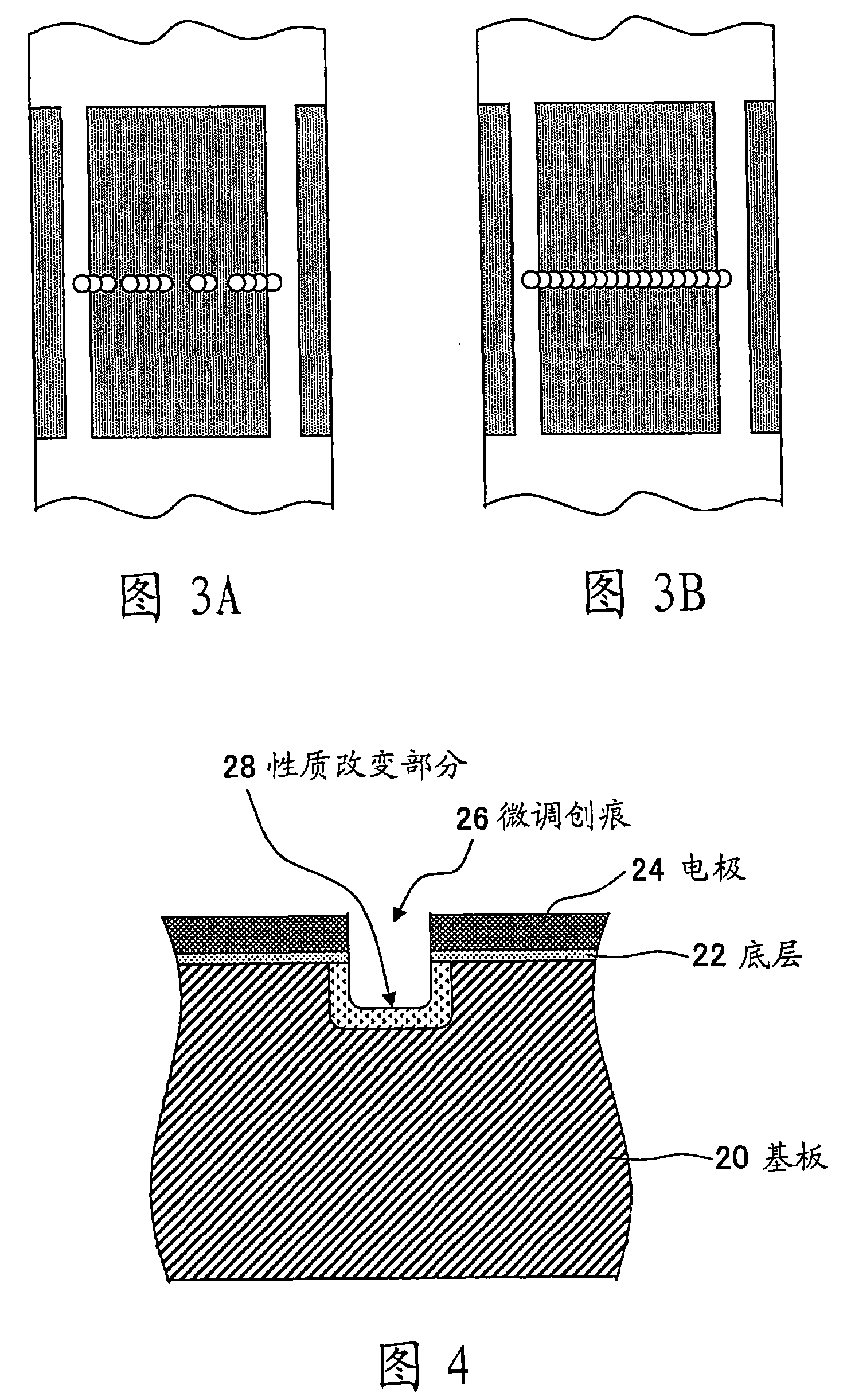
[0035] First, the principle of a laser processing method according to an embodiment of the present invention will be described with reference to FIGS. 2 to 4 .

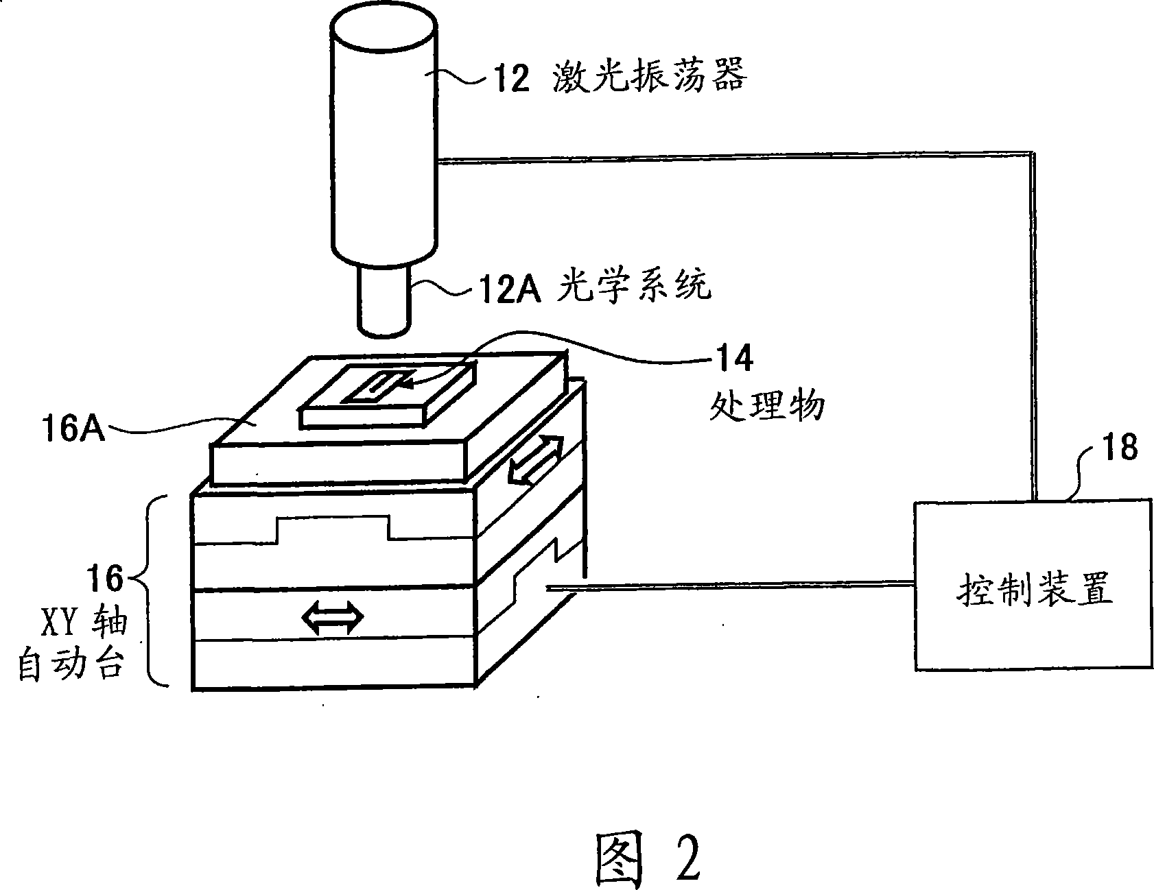
[0036] FIG. 2 is a diagram illustrating a laser processing apparatus performing a laser processing method according to an embodiment of the present invention.

[0037] The laser processing apparatus illustrated in FIG. 2 is particularly suitable for processing parts of small devices, and includes a laser oscillator 12 that oscillates a laser beam and an XY-axis automatic table 16 that holds a processing object (workpiece) 14 in place. It should be noted that the operations of the laser oscillator 12 and the XY-axis automatic table 16 are controlled by the control device 18 .

[0038]The laser oscillator 12 may be a laser such as a YAG laser, which oscillates a relatively high-power laser beam t...


PUM

PropertyMeasurementUnit
diameteraaaaaaaaaa

Abstract

The invention discloses a device manufacturing method, a laser processing method, and a laser processing apparatus. The device manufacturing method includes the steps of moving a device at a constant speed while irradiating a laser beam on the device, and processing a part of the device with the laser beam.

Description

technical field [0001] The present invention relates to a method of manufacturing a small device, a laser processing method for processing components of a small device using laser light, and a laser processing apparatus for realizing such a laser processing method. Background technique [0002] Along with the miniaturization of electronic equipment, there is an increasing demand for miniaturization of small devices used in electronic equipment. Therefore, there is a need for processing techniques that enable precise processing of microstructures. For example, as an example of a small device used in electronic equipment, a vibration gyroscope may be installed in a car navigation system as an angular velocity sensor (gyro sensor). [0003] The vibrating gyroscope is a position detection sensor that includes a vibrating fork made of a piezoelectric material as a sensing element, and detects a current position using Coriolis force acting on the vibrating fork as it rotates. A ...

Claims


Application Information

Patent Timeline
Patent Type & Authority Applications(China)
IPC IPC(8): B23K26/00B23K26/08B23K26/02B23K26/046B23K26/351B23K26/361B23K101/36H01S3/00
CPCB23K26/0003G01C19/5607Y10T428/24802B23K26/351
Inventor 嶋田淳吾十仓史彦野村进直
Owner FUJITSU LTD
Why Eureka
Eureka Blog
Learn More