Vapor seal drawing liquid non-contact type hydrojet grinding wheel for numerical control relief polishing

A non-contact, polishing liquid technology, which is applied in the direction of optical surface grinder, grinding/polishing equipment, grinding machine, etc., can solve the problems of affecting the polishing accuracy, eroding the non-polishing area, and the polishing liquid cannot be collected in time, so as to avoid local Effects of stress, quality improvement, uniformity assurance

Inactive Publication Date: 2008-08-20
CHANGCHUN INST OF OPTICS FINE MECHANICS & PHYSICS CHINESE ACAD OF SCI
View PDF1 Cites 17 Cited by
  • Summary
  • Abstract
  • Description
  • Claims
  • Application Information

AI Technical Summary

Problems solved by technology

[0005] The main problem of the liquid jet grinding head is that the polishing liquid used in the processing process cannot be collected in time, which will erode the non-polishing area of ​​the processed optical element and affect the polishing accuracy

Method used


Image

  • Vapor seal drawing liquid non-contact type hydrojet grinding wheel for numerical control relief polishing
  • Vapor seal drawing liquid non-contact type hydrojet grinding wheel for numerical control relief polishing
  • Vapor seal drawing liquid non-contact type hydrojet grinding wheel for numerical control relief polishing

Examples


Embodiment Construction

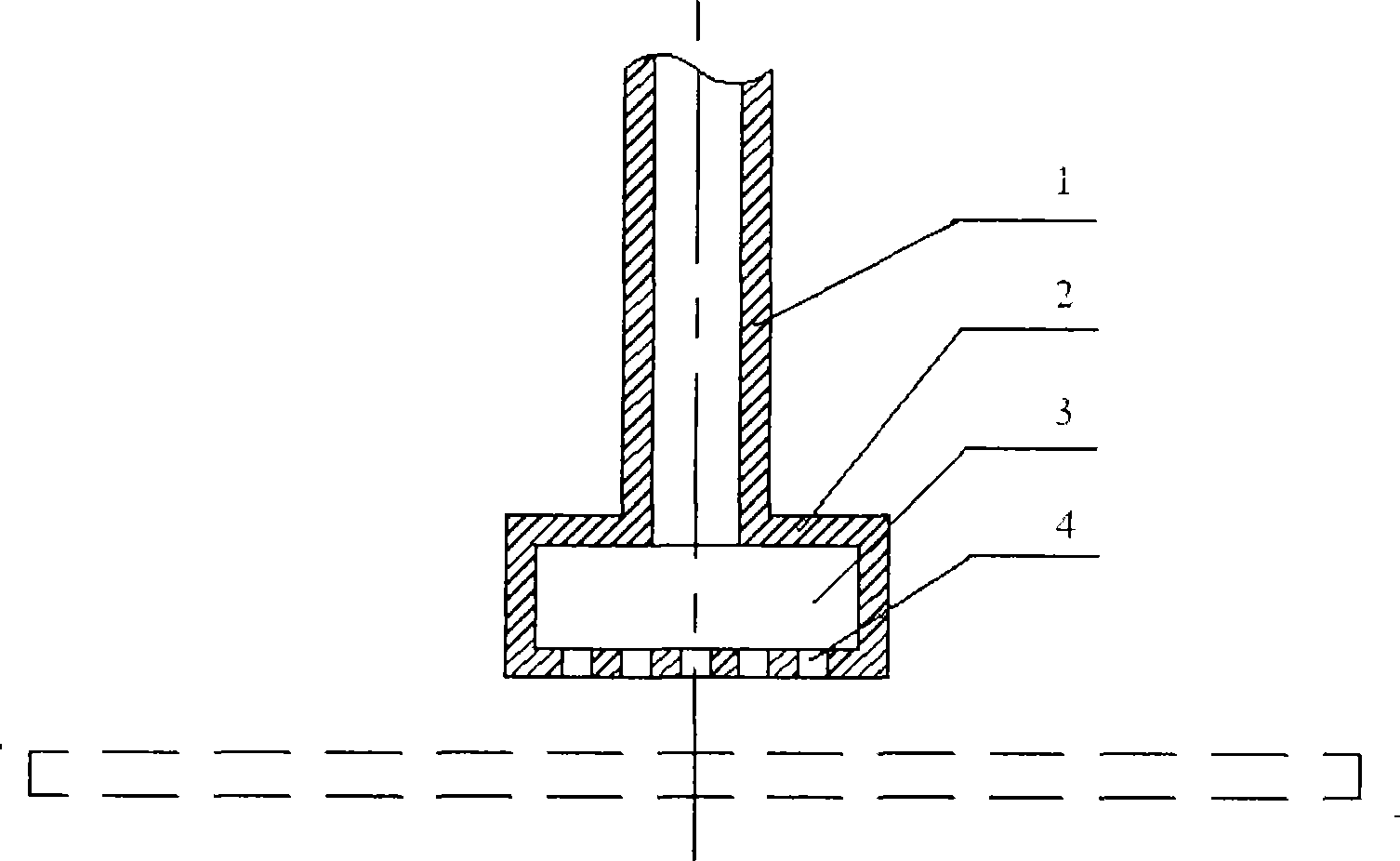
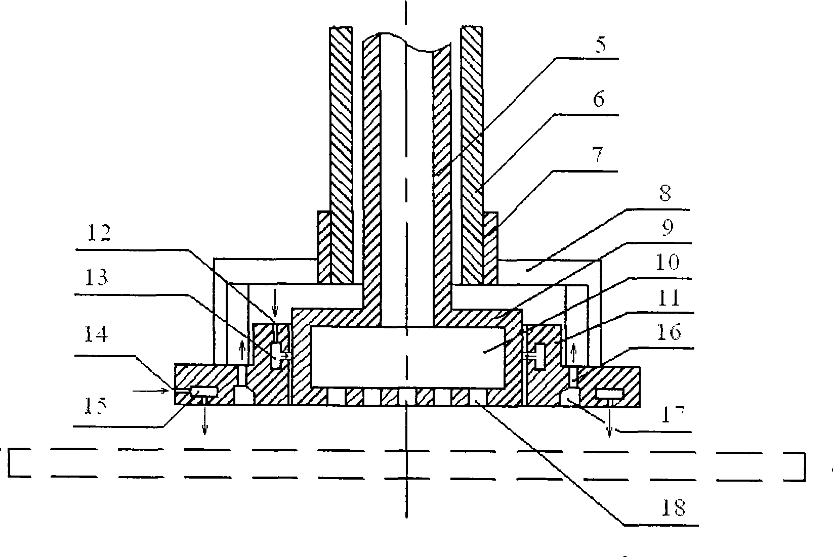
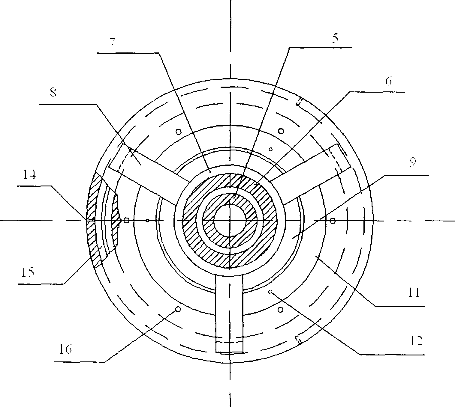
[0014] The invention according to figure 2 and image 3 The structure shown is implemented. Wherein the hollow drive shaft 5, the grinding head shaft sleeve 6, the grinding head connecting sleeve 7, the collecting tray connecting frame 8, the hollow grinding head 9, and the polishing fluid collecting tray 11 are made of stainless steel. Hollow driving shaft 5 and hollow grinding head 9 are integral hollow parts or two parts are for coordinating hollow parts, and so-called cooperation is that two parts are glued or threaded. The grinding head axle sleeve 6 is connected with the grinding head connecting sleeve 7 by bolts or threads. The connection between the collecting plate connecting frame 8 and the grinding head connecting sleeve 7 and the polishing liquid collecting plate 11 is welded. The size of the polishing liquid collecting disc 11 is related to the size of the hollow grinding head 9, generally twice the size of the hollow grinding head, and the gap between the pol...


PUM


Abstract

The invention relates to a non-contact spray-grinding wheel head of airtight suction air for numerical controlled polishing, belonging to the cold machining technical field in optics. The invention e is to provide solution of a non-contact spraying grinding wheel head of airtight suction air for numerical controlled polishing. The non-contact spray-grinding wheel head comprises a hollow grinding wheel head, a plurality of outlets of the polishing liquid, a connection support and a catch tray of the polishing liquid, an air inlet, a air curtain groove, a hole for liquid suction, a collecting tank and other members, which is characterized in that: the catch tray of the polishing liquid is fixedly connected with the shaft sleeve of the grinding wheel head through the connection support of the catch tray and is sleeved on the hollow grinding wheel head; the first air inlet and the first air curtain groove of the catch tray are communicated with each other; the first air curtain groove is communicated with the interspaces between the hollow grinding wheel head and the catch tray; the second air inlet and the second air curtain groove of the catch tray are communicated with each other; the second air curtain groove is communicated with the lower working surface of the catch tray; the collecting tank is on the lower working surface of the catch tray; the hole for liquid suction on the collecting tank is communicated with the out space of the catch tray; the outlets of the polishing liquid are distributed on the working surface of the hollow grinding wheel head.

Description

technical field [0001] The invention belongs to the technical field of optical cold processing and relates to a gas-sealed liquid pumping non-contact liquid spray grinding head for numerical control polishing. Background technique [0002] In the field of optical technology, the optical lenses that make up various optical systems, such as lenses, plane mirrors, spherical mirrors, various aspheric mirrors, etc., need to be subjected to rough grinding, fine grinding, fine grinding, polishing and other grinding according to the technical requirements of optical design. Production, this process is called optical cold processing in the optical field. [0003] Optical cold processing machine tools have grinding heads for grinding and manufacturing optical lenses. In general, the grinding head used for CNC polishing is smaller than the grinding head for mechanical polishing, and they are all solid grinding heads. [0004] The closest existing technology to the present invention i...

Claims


Application Information

Patent Timeline
Patent Type & Authority Applications(China)
IPC IPC(8): B24B13/00B24B41/04B24B57/02
Inventor 巩岩张巍
Owner CHANGCHUN INST OF OPTICS FINE MECHANICS & PHYSICS CHINESE ACAD OF SCI
Why Eureka
Try Eureka