
Press moveable platform for elastic element unloading

A technology of moving workbench and elastic components, which is applied in the field of presses, can solve the problems of many links in the guiding mechanism, large lifting stroke of the workbench, affecting the appearance of the press, etc., and achieves simple structure, small deformation, and long glass fiber reinforced response The effect of injection molding

Active Publication Date: 2008-08-20
扬州市邗江扬子汽车内饰件有限公司
View PDF0 Cites 14 Cited by
  • Summary
  • Abstract
  • Description
  • Claims
  • Application Information

AI Technical Summary

Problems solved by technology

[0015] ① The overall structure is relatively complex, especially the lifting mechanism of the worktable used to withstand sufficient forming pressure or clamping force needs to be driven by four oil cylinders. The synchronization accuracy of the oil cylinders brings great pressure to the design and manufacture. The setting of oil pipes Also affects the appearance of the press;
[0016] ② There are many links in the guiding mechanism itself, and at the same time, it is limited by the guiding method, resulting in low guiding accuracy;
[0017] ③The lifting stroke of the worktable is relatively large, which affects the effective working stroke and application range of the press
[0023] Due to its inherent defects, the movable table of the existing press cannot meet the long glass fiber reinforced reaction injection molding process of automotive trim parts

Method used


Image

  • Press moveable platform for elastic element unloading
  • Press moveable platform for elastic element unloading
  • Press moveable platform for elastic element unloading

Examples


Embodiment Construction

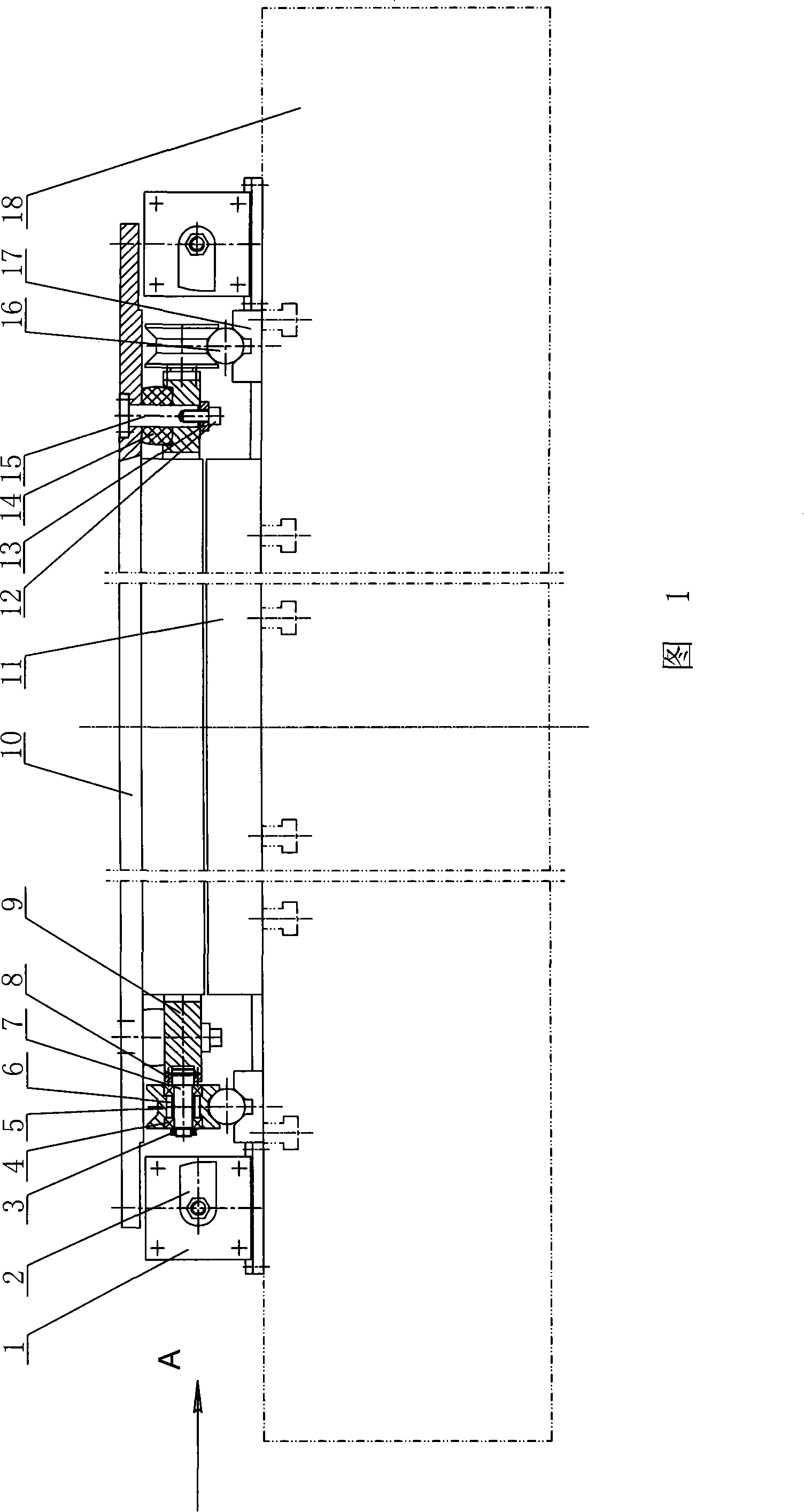
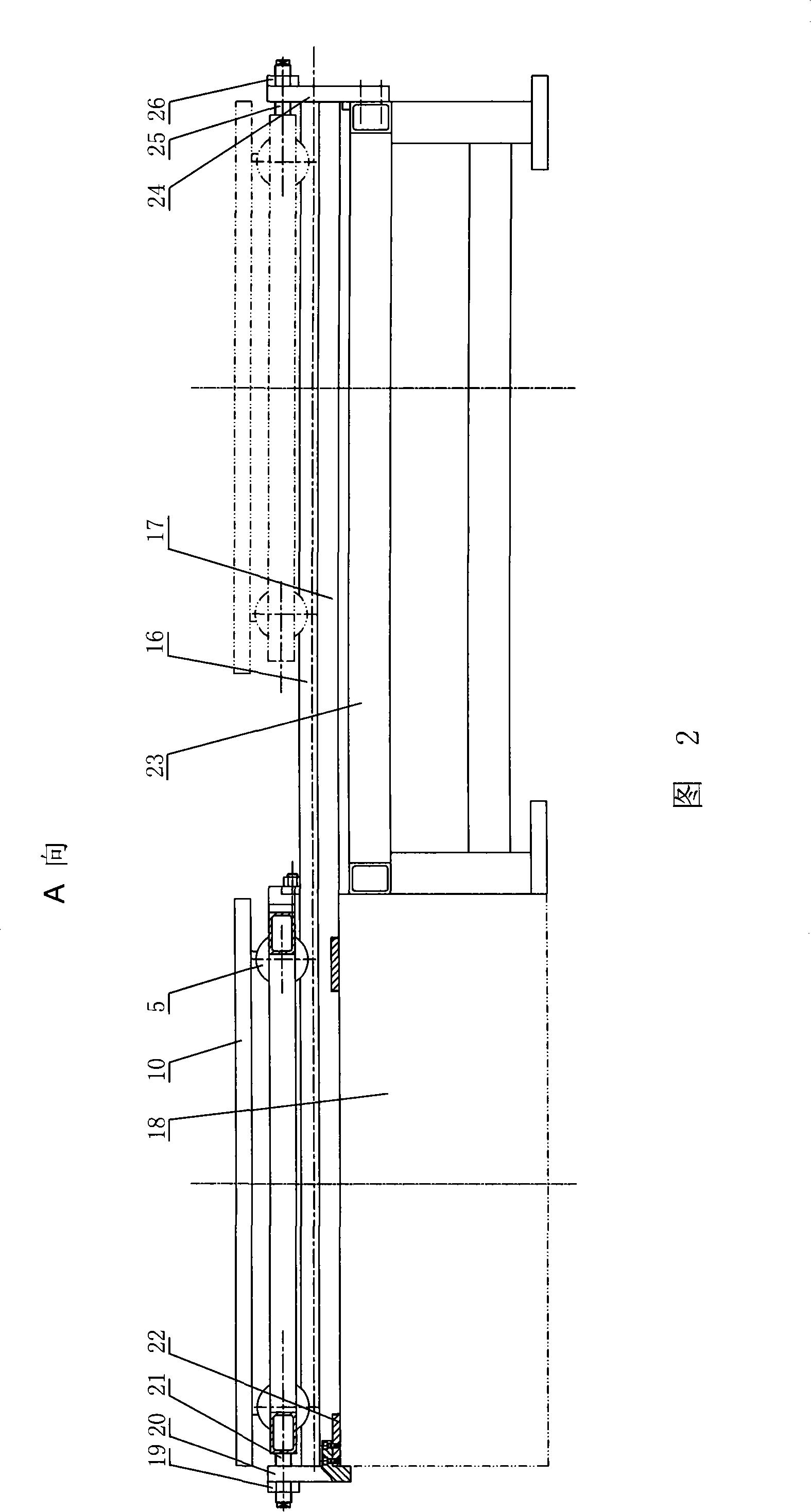
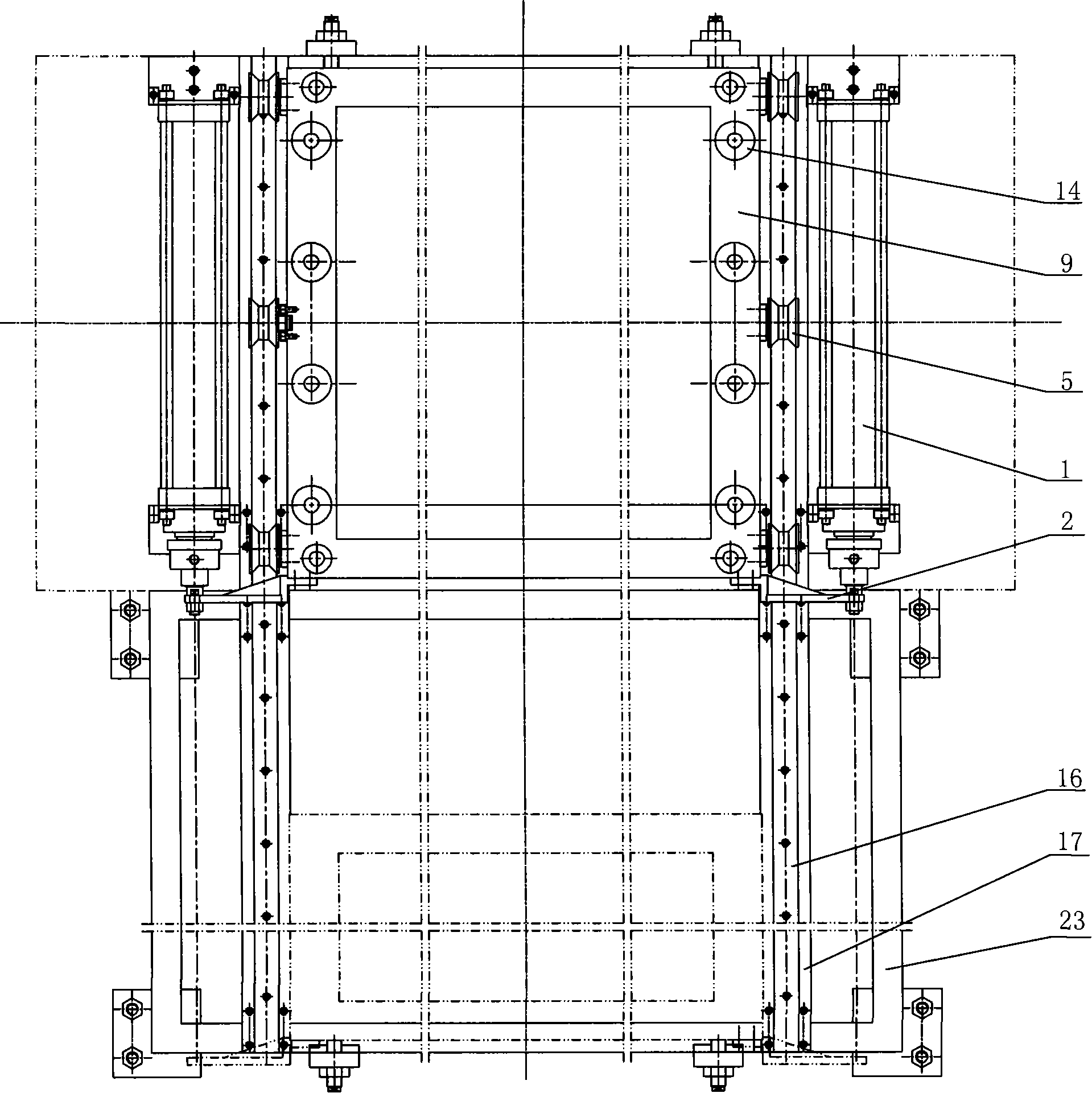
[0034] As shown in the figure, the movable workbench of the press for unloading the elastic element includes a worktable 10, a movable bracket 9 is arranged under the worktable 10, and a guide rod 15 is used between the worktable 10 and the movable bracket 9 Guide, the guide rod 15 is set with a pre-compressed elastic element 14, the elastic element 14 can be a polyurethane rubber plate or a coil spring, a disc spring, etc. 9, in order to realize the pre-compression of the elastic element 14, the lower end of the guide rod is provided with a baffle 13, the baffle 13 is attached to the lower side of the moving bracket 9, the screw 12 passes through the baffle 13 and is connected with the lower end of the guide rod, and the screw is tightened 12. The elastic element 14 can be compressed to realize the pre-compression of the elastic element 14. The pre-compression amount of the elastic element 14 should ensure that its load-bearing capacity can be enough to hold up the worktable a...


PUM


Abstract

The invention discloses a moving worktable of the pressing machine of the elastic element unloading in the pressing machine field, which comprises a working plate, and a moving supporting bracket is arranged under the working plate. A leader is used to guide between the working plate and the moving supporting bracket, a pre-compressing elastic element is sleeved on the leader, and the upper and lower ends of the elastic element are respectively propped on the working plate and the moving supporting bracket. Rollers are arranged at two sides of the moving supporting bracket, and the rollers are supporting on the linear guide of the circular cross-section. Cylinders or hydraulic cylinders are respectively arranged at two sides of the moving supporting bracket, and the cylinder bodies of the cylinders or the hydraulic cylinders are fixed with the bed, and the piston extending end of the cylinder or the hydraulic cylinder is fixed with the moving supporting bracket. A padding plate is arranged under the working plate, and an obligated clearance is arranged between the two. When the worktable endures the function of the clamping force, the elastic element is compressed, and the working plate is pressed on the padding plate directly. The moving worktable of the pressing machine has the advantages of enabling the molds to move between two stations and locate automatically, supporting a certain clamping force, and satisfying the reinforcing reaction for injection forming of the long glass fiber of the automobile ornament.

Description

technical field [0001] The invention relates to a press, in particular to a workbench of the press. Background technique [0002] In the general pressure forming process, the workbench of the press has the following two forms: [0003] (1) The workbench of the press is fixed [0004] When this kind of press is working, the process equipment for forming is directly installed on the fixed workbench, and the clamping pressure during the forming process is directly transmitted to the press body through the mold, and there is no problem of movement or positioning of the workbench. [0005] (2) The worktable of the press can be moved [0006] This kind of press is mainly to meet the needs of the forming process. The workbench generally has two stations, and one station is used for various auxiliary operations, such as cleaning the mold, loading materials, and taking parts. [0007] In order to realize the movement and positioning of the workbench between the two stations, the w...

Claims


Application Information

Patent Timeline
Patent Type & Authority Applications(China)
IPC IPC(8): B30B15/04
Inventor 王栓虎孙宇丁韧刘国斌顾荣吉会明
Owner 扬州市邗江扬子汽车内饰件有限公司
Learn More