Backlight module, LCD device and method for improving brightness of backlight source

A technology for the brightness of liquid crystal display devices and backlight sources, which is applied in the fields of optics, nonlinear optics, instruments, etc., can solve the problems of poor uniformity of surface light sources and light leakage, and achieve the effect of increasing brightness and improving display quality.

Inactive Publication Date: 2008-08-20
INNOLUX CORP
View PDF0 Cites 0 Cited by
  • Summary
  • Abstract
  • Description
  • Claims
  • Application Information

AI Technical Summary

Problems solved by technology

[0009] Similar to the above-mentioned backlight module 100a, when the cold cathode fluorescent lamp tube 120 is placed close to the bottom 113 of the lampshade, the brightness of the surface light source provided by the backlight module 100b is optimal, but due to the capacitive effect, the uniformity of the surface light source will be reduced. become worse
In addition, since there is a gap between the lampshade 110b and the light guide plate 130b, when the cold cathode fluorescent lamp 120 is placed close to the light incident surface 114 of the light guide plate 130b, part of the light emitted by the cold cathode fluorescent lamp 120 (such as light 121 ) easily pass through the gap 50 between the lampshade 110b and the light guide plate 130b, resulting in light leakage

Method used


Image

  • Backlight module, LCD device and method for improving brightness of backlight source
  • Backlight module, LCD device and method for improving brightness of backlight source
  • Backlight module, LCD device and method for improving brightness of backlight source

Examples


no. 1 example

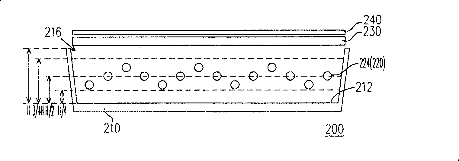
[0079] figure 2 It is a schematic cross-sectional view of a backlight module according to the first embodiment of the present invention, image 3 yes figure 2 A schematic diagram of the connection between a light source and the inverter, and Figure 4 yes figure 2 Schematic diagram of the first light source and the bottom of the light box. Please refer to Figure 2 to Figure 4 , the backlight module 200 of this embodiment is a direct type backlight module, which includes a light box 210 , a plurality of light sources 220 and a diffuser plate 230 . Wherein, the light box 210 has a bottom 212 and a light exit section 216 opposite to each other, and the distance between the bottom 212 of the light box 210 and the light exit section 216 is H. In addition, the light source 220 is disposed in the light box 210 , and the diffusion plate 230 is disposed above the light emitting section 216 of the light box 210 . Each light source 220 has a first end 224 and a second end 226 ....

no. 2 example

[0086] Figure 7 is a schematic cross-sectional view of a backlight module according to the second embodiment of the present invention, and Figure 8 yes Figure 7 A schematic diagram of the connection between a light source and an inverter. Please refer to Figure 7 and Figure 8 , the backlight module 300 of this embodiment is a side-illuminated backlight module, which includes a lampshade 310 , a plurality of light sources 320 and a light guide plate 330 . Wherein, the lampshade 310 has a bottom 312 and a light emitting section 316 opposite to each other, and the distance between the bottom 312 of the lampshade 310 and the light emitting section 316 is H. The light guide plate 330 is arranged beside the light emitting section 316 of the lampshade 310 , and the light source 320 is arranged inside the lampshade 310 . In addition, each light source 320 has a first end 324 and a second end 326 . In order to enhance the brightness of the backlight source provided by the ba...

no. 3 example

[0093] Figure 9 It is a schematic diagram of a liquid crystal display device according to the third embodiment of the present invention. Please refer to Figure 9 , the liquid crystal display device 400 of this embodiment includes a backlight module 484 and a liquid crystal display panel 490 . The backlight module 484 is disposed on one side of the liquid crystal display panel 490 to provide the light source required by the liquid crystal display panel 490 . Wherein, the liquid crystal display panel 490 includes an upper substrate 492 , a lower substrate 494 and a liquid crystal layer 496 arranged between the upper substrate 492 and the lower substrate 494 . The upper substrate 492 can be a color filter substrate, and the lower substrate 494 can be a TFT array substrate. In addition, the backlight module 484 is the direct type backlight module described in the first embodiment or the side light type backlight module described in the second embodiment.

[0094] Since the b...


PUM


Abstract

A backlight mould comprises a lamp box, a plurality of lamp source and a diffusing plate. Wherein, the lamp box has opposite a bottom and a out optical cross-section, and the distance from the bottom to the out optical cross-section is H. The lamp source is configured in the lamp box, and the diffusing plate is configured on the out optical cross-section of lamp box. Each lamp source has a first end and a second end, the distance from first end of each lamp box to the bottom of lamp is in the range of 1 / 4 H-3 / 4 H, and at least one distance from first end of lamp source to the bottom is different to other distances. Furthermore, the invention provides another LCD device and a method for hoisting backlight source lightness.

Description

technical field [0001] The present invention relates to a backlight module and a liquid crystal display device, in particular to a backlight module capable of taking into account the brightness and uniformity of a surface light source, and a liquid crystal display device with the backlight module. Background technique [0002] Due to the continuous improvement and advancement of technology, the era of digital multimedia video has come, and the demand for various video and imaging devices has also increased significantly. The traditional cathode ray tube (Cathode RayTube, CRT) has the advantages of excellent display quality and economy, but its volume is too large, it takes up too much space, coupled with the gradual rise of environmental protection awareness of energy conservation, and the radiation of the cathode ray tube is relatively large. Due to the problems of high image quality, low power consumption, and low radiation, liquid crystal displays have gradually replaced ...

Claims


Application Information

Patent Timeline
Patent Type & Authority Applications(China)
IPC IPC(8): G02F1/13357G02F1/1333G02F1/1335
Inventor 陈春诚许世民
Owner INNOLUX CORP
Why Eureka
Try Eureka