

Ureter bracket
A ureter and tube technology, which is applied in the field of surgical auxiliary materials, can solve the problems of blockage of peripheral small holes and central holes of the tube, limited number and small pore diameter, etc.
Inactive Publication Date: 2008-08-27
西安远大德天药业股份有限公司
View PDF0 Cites 13 Cited by
- Summary
- Abstract
- Description
- Claims
- Application Information
AI Technical Summary
Problems solved by technology
However, because the existing ureteral stent is perforated around the stent tube, its aperture is small and the number is limited. During the drainage process, it is easy to form urine crystals, so that the peripheral small holes and the central hole of the tube are blocked by crystals or foreign objects, resulting in failed urine drainage
Method used
View moreImage
Smart ImageViewing Examples

Examples
Embodiment Construction
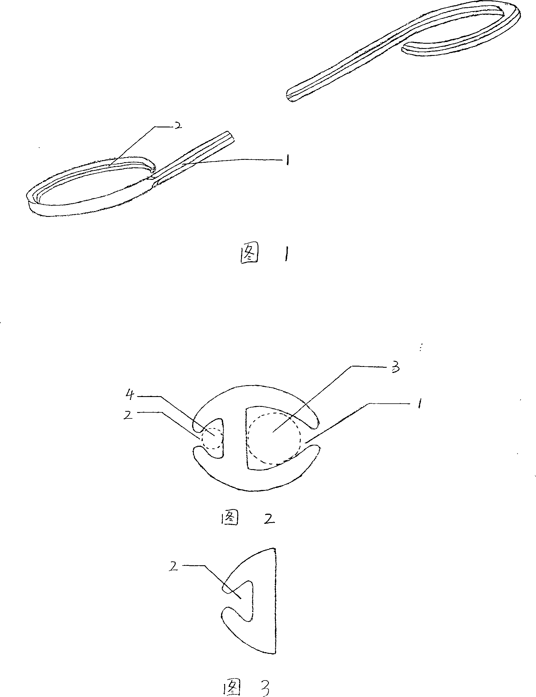
[0011] The present invention is composed of a tube made of medical polymer material. The ends of the tube are bent inwards in opposite directions to form a circle, shaped like a pig's tail. There is a large groove 1 on the side of the tube, and the other side of the tube is opposite. There is a smaller groove 2 on one side, and its cross section is a pseudo "H" type. The pipe diameter is 1.4-3.2mm and the length is 180-290mm. The diameter 3 of the larger groove 1 is 0.8-2.0mm, and the diameter 4 of the smaller groove 2 is 0.4-0.8mm. One of the ends of the tube bent into a circle does not have the larger groove 1 side, only the smaller groove 2 side.
Login to View More PUM
| Property | Measurement | Unit |
|---|---|---|
| Diameter | aaaaa | aaaaa |
| Length | aaaaa | aaaaa |
| Diameter | aaaaa | aaaaa |
Abstract
The invention discloses a ureteral stent, which comprises a tubular body made of medical-grade polymer materials, wherein the ends of the tubular body are inwardly bent in opposite directions to a pigtail shape, and a larger groove (1) and a smaller groove (2) are symmetrically arranged at side walls of the tubular body with H-shaped cross sections. The diameter of the tubular body is 1.4-3.2 and the length thereof is 180-290 mm. The diameters of the larger (1) and the smaller (2) grooves are 0.8-2.0 mm and 0.4-0.8 mm respectively. One of the two pigtail-shaped ends has only the smaller groove (2) side, without the larger groove (1) side. The special open H-shaped structure can prevent blockage due to urine crystals when draining urine, so that the urine can be drained into bladder smoothly.
Description
technical field [0001] The invention belongs to auxiliary materials for surgical operations, in particular for ureteral operations in urology. Background technique [0002] Ureteral stent, also known as pigtail tube or double "J" tube, is a tube commonly used in urology to drain urine and is generally used for kidney stones, ureteral stones, kidney transplantation, hydronephrosis, kidney and ureter tumor surgery and ureter Stenosis during dilation surgery. It can also drain urine, prevent ureteral stricture and tumor from compressing the ureter, etc. However, because the existing ureteral stent is perforated around the stent tube, its aperture is small and the number is limited. During the drainage process, it is easy to form urine crystals, so that the peripheral small holes and the central hole of the tube are blocked by crystals or foreign objects, resulting in Failure to drain urine. Contents of the invention [0003] The purpose of the present invention is to provi...
Claims
Login to View More Application Information
Patent Timeline
 IPC IPC(8): A61F2/82A61F2/04A61F5/44A61M1/00A61M27/00
CPCA61M27/008
Inventor周明非朱望李娅曹庆民赵秀丽邢玉斌魏华
Owner西安远大德天药业股份有限公司