Real time binocular vision guidance method facing to underwater carrying vehicle
An underwater vehicle, binocular vision technology, applied in instruments, line-of-sight measurement, mapping and navigation, etc., can solve problems such as increased matching error and inaccurate ranging.
- Summary
- Abstract
- Description
- Claims
- Application Information
AI Technical Summary
Problems solved by technology
Method used
Image
Examples
example 1
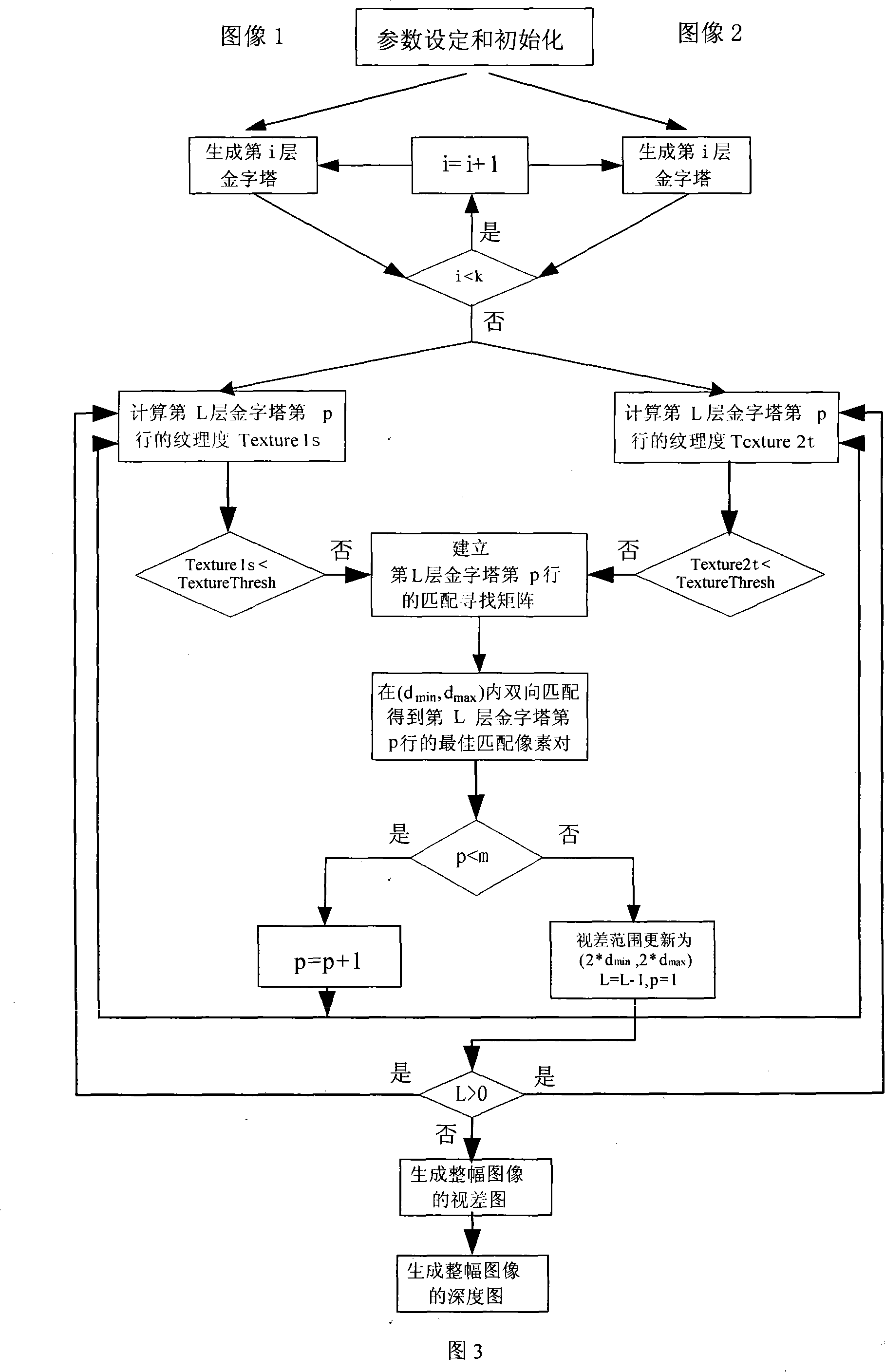
[0081]Experiments were performed using the widely used Tsukuba synthetic stereo image pairs. The Tsukuba stereo image pair has been rectified and has a size of 384×288. Its real disparity map is shown in Figure 6(b). In the experiment, the pyramid series k=4, the zoom ratio is r=2, the matching window is 15×15, the NCC threshold is 0.5, the parallax range is (0, 40), and the texture threshold is 0.1. On the Pentium 42.40GHz industrial computer, the stereo matching is calculated The parallax process took an average of 164.5ms. The NCC value can be used to measure the matching accuracy. The obtained disparity map and NCC map are shown in Fig. 7 .
example 2
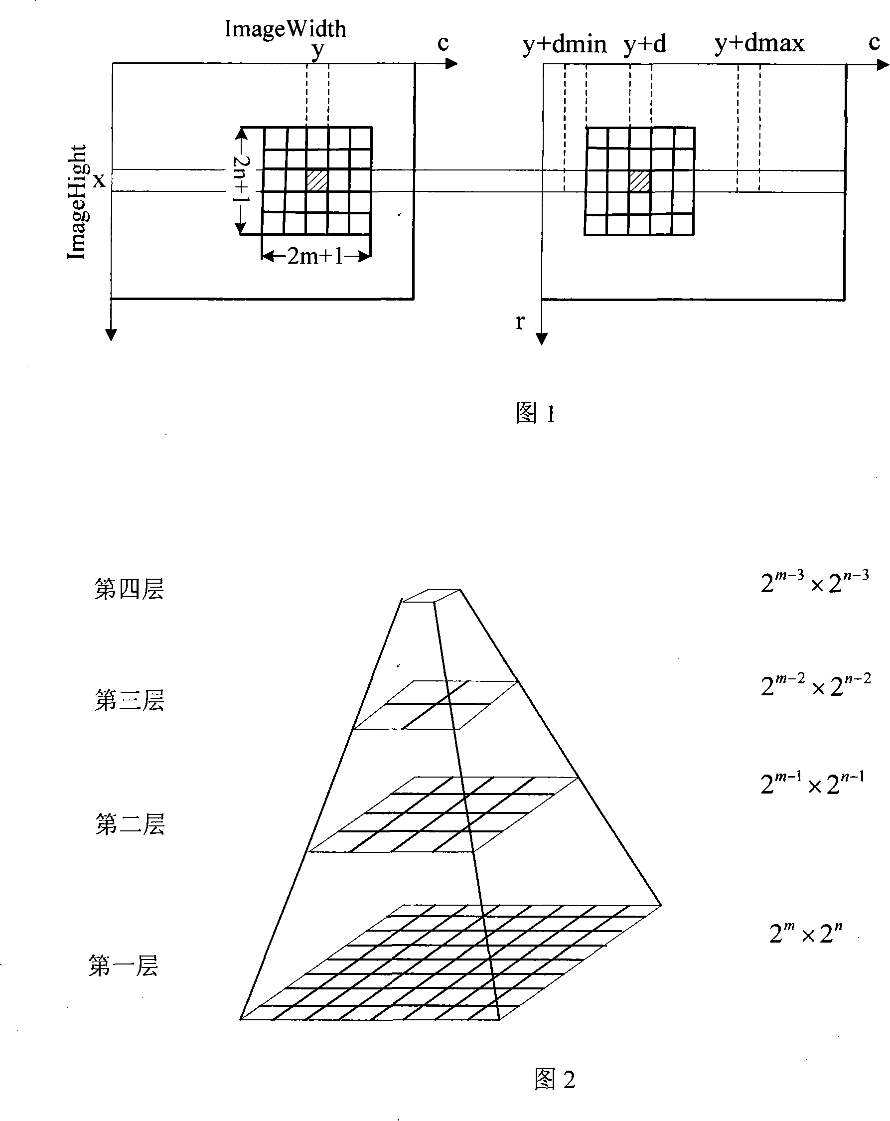
[0083] Experiments are carried out in a simulated autonomous underwater vehicle (AUV for short) motion environment. The resolution of the two industrial digital CCD cameras is 1280×1024. On the basis of accurate calibration, the captured image pair is corrected first, and then the above method is used to set the pyramid level k=4, the zoom ratio is r=2, the matching window is 21×21, the NCC threshold is 0.85, and the parallax range is (- 230, -200), Texture Threshold 15. The average time spent on obtaining the disparity map by running the program on the same industrial computer is only 258ms, and the accuracy of the obtained depth map can reach millimeter level. See Figure 8 for the corrected image pair, and Figure 9 for the disparity map and NCC map. It can be seen from Figure 9 that the pyramid NCC algorithm based on texture control effectively extracts the depth of obstacles from the simulated ocean environment. The calculation time of 258ms proves that this method has pr...
example 3
[0085] Using this binocular vision guidance system, a simulation test of AUV space obstacle avoidance was carried out in the laboratory. The experiment was carried out on a four-degree-of-freedom AUV simulated motion platform. The platform is driven by four high-precision stepping motors, which can well simulate the advance and retreat, lateral movement, heave and head turn of the AUV in the marine environment. The entire obstacle avoidance simulation system is composed of three parts: binocular guidance system, obstacle avoidance control system and executive mechanism - AUV simulation motion platform and peripheral equipment.
[0086] As shown in Figure 10, the binocular camera is fixed on the front end of the AUV motion model, and a spherical obstacle and a square obstacle with a straight surface are placed on its walking path. The spherical obstacle is located to the left of the AUV's initial position, and the square obstacle is located to the right of the AUV. When the s...
PUM
 Abstract
Description
Claims
Application Information
 - R&D
- Intellectual Property
- Life Sciences
- Materials
- Tech Scout
- Unparalleled Data Quality
- Higher Quality Content
- 60% Fewer Hallucinations
Browse by: Latest US Patents, China's latest patents, Technical Efficacy Thesaurus, Application Domain, Technology Topic, Popular Technical Reports.
© 2025 PatSnap. All rights reserved.Legal|Privacy policy|Modern Slavery Act Transparency Statement|Sitemap|About US| Contact US: help@patsnap.com


