Backlight device and transmission type display apparatus

A backlight device, transmission type technology, applied in lighting devices, lighting device parts, optics, etc., can solve the problems of display angle tilt, display darkening, difficult to use display panels, etc.

Active Publication Date: 2008-08-27
MITSUBISHI ELECTRIC CORP
View PDF2 Cites 33 Cited by
  • Summary
  • Abstract
  • Description
  • Claims
  • Application Information

AI Technical Summary

Problems solved by technology

[0006] Although in the display device shown in Patent Document 1, as long as two different images are repeated and rewritten on the liquid crystal panel in synchronization with the lighting switching of the light sources respectively arranged on the two different light incident end faces of the light guide plate, Users who watch from the normal direction of the display surface to 15 degrees to the left and users who watch to the right 15 degrees respectively watch different images, but there is a problem when the main user is facing directly When the panel is displayed, two images are mixed together in the front direction
[0007] In addition, the liquid crystal display panel of Patent Document 2 is provided with a parallax barrier so that an image for a left observer and an image for a right observer are displayed on the pixel formation layer, and the light emitted from each image is guided to the left and right respectively. Viewers on the side and right, so there is a problem that the display angle is tilted, and it is difficult to use when facing the display panel
In addition, since the image forming layer is divided into left and right observers, it becomes an image with half the number of pixels, and there is a problem that the display becomes dark because part of the transmitted light is blocked by the parallax barrier.

Method used


Image

  • Backlight device and transmission type display apparatus
  • Backlight device and transmission type display apparatus
  • Backlight device and transmission type display apparatus

Examples


Embodiment approach 1

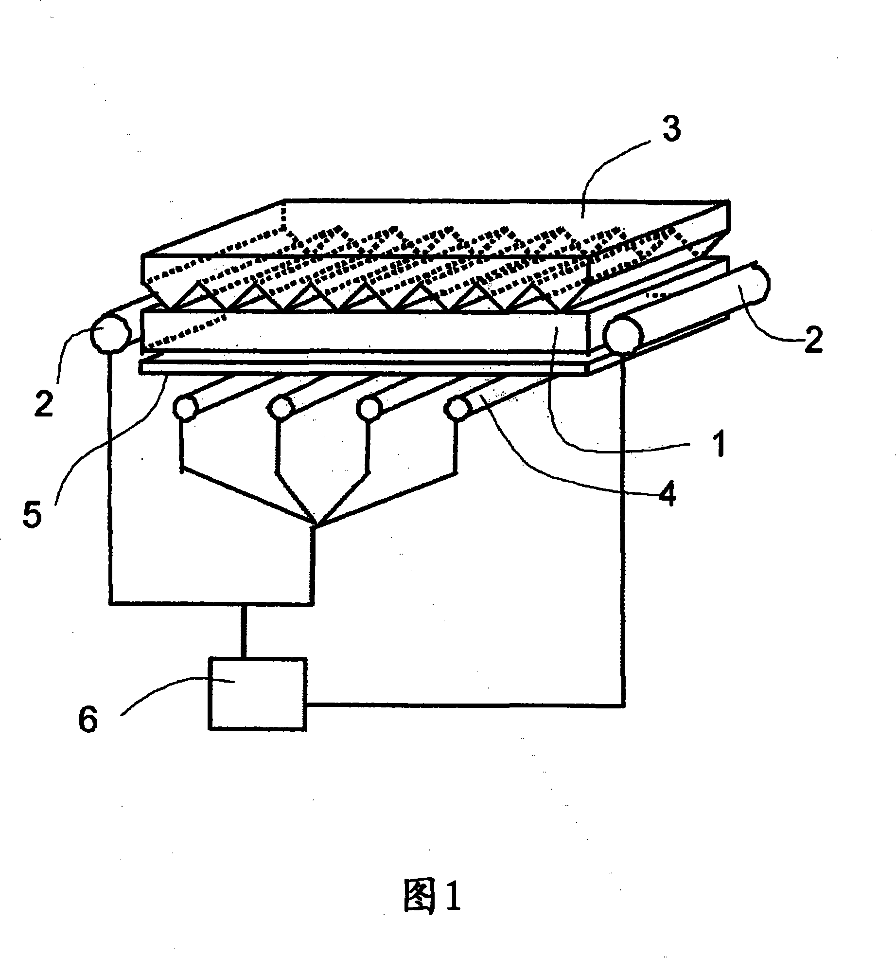
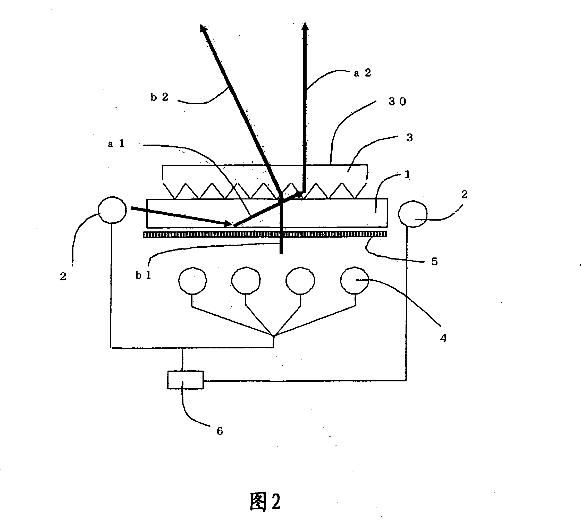
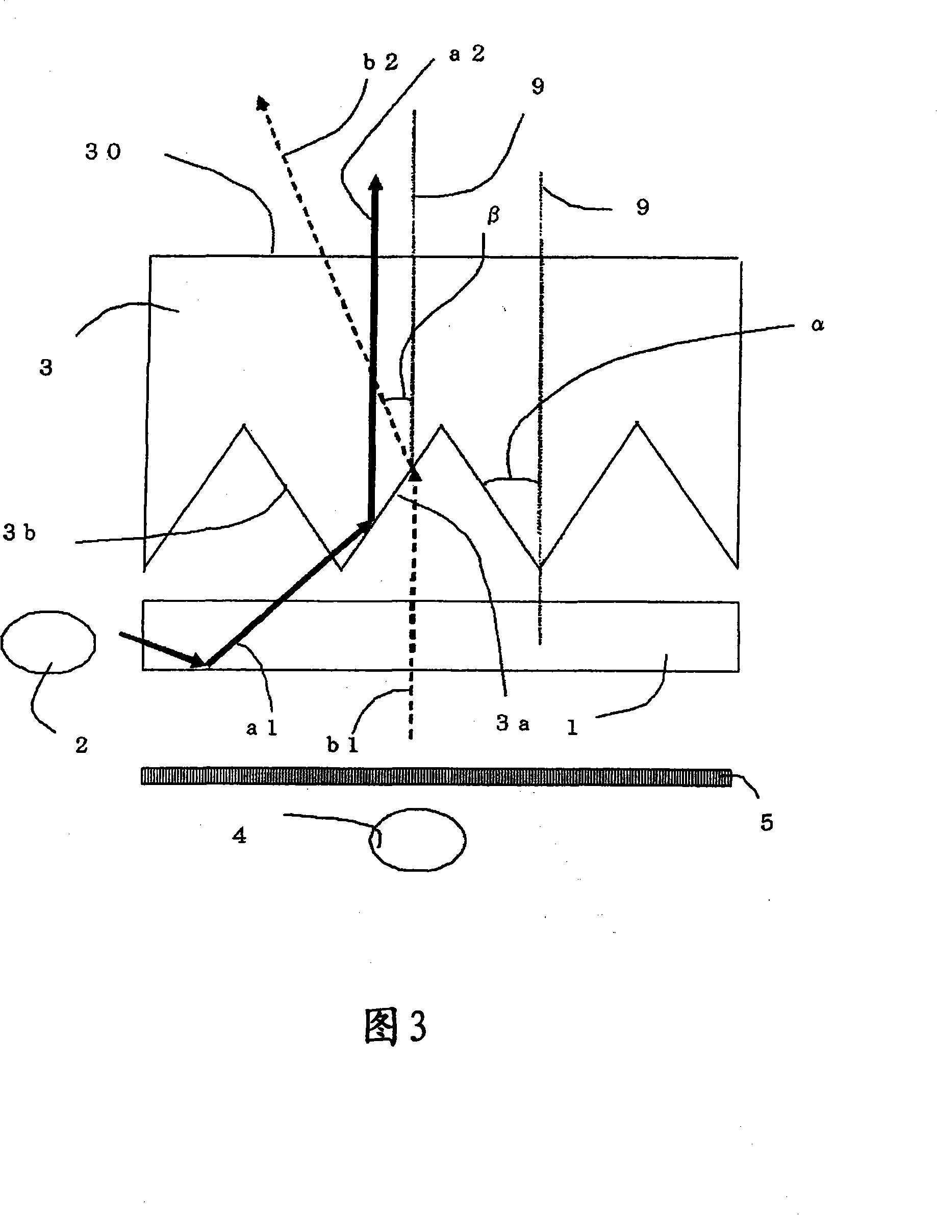
[0039] FIG. 1 is a perspective view of a backlight device according to Embodiment 1 of the present invention. FIG. 2 is an explanatory diagram showing a transmitted optical path of light from the light source in FIG. 1 , and is a cross-sectional view using a plane perpendicular to the ridgeline direction of the triangular prism array of the prism sheet.

[0040] The first light source 2 is arranged respectively on the different two end face sides of the first light guide plate 1, the first prism sheet 3 is set on the light extraction side (exit side) of the first light guide plate 1, and the first light guide plate 1 On the side opposite to the first prism sheet 3 , the second light source 4 is arranged with the viewing angle adjustment film 5 interposed therebetween. In addition, a light source control unit 6 is provided to perform brightness adjustment or blink switching of the lights from the first light source 2 and the second light source 4 .

[0041] As the first light ...

Embodiment approach 2

[0060] Use the first prism sheet 3 that the apex angle of triangular prism row is respectively 70 degree, 65 degree, 60 degree or 55 degree, as incident light b1 from the second light source 4 incident to the first prism sheet 3, use in the normal direction Light having directivity and having an angular distribution between -35° and 35° with respect to the normal direction, that is, light having an angular distribution of 70° around the normal direction, is subjected to the same process as in the first embodiment. The simulation of the angular distribution of each outgoing light when the light of the first and second light sources is emitted on each of the above-mentioned first prism sheets 3 .

[0061] 7 to 10 are the simulation results of the angular distribution of the outgoing light b2 emitted on each of the first prism sheets 3 in the case of using the first prism sheet 3 having triangular prism rows with different apex angles. , that is, the angular distribution of the i...

Embodiment approach 3

[0066] Using the first prism sheet 3 having a triangular prism array having an apex angle of 60 degrees in Embodiment 1, the light b1 incident on the first prism sheet 3 from the second light source 4 has directivity in the normal direction, and Relative to the normal direction at -20° to 20°, -30° to 30°, -35° to 35°, -40° to 40°, -45° to 45°, or -50° to 50° In the case of having an angular distribution, that is, having an angular distribution with a width of 40 degrees, 60 degrees, 70 degrees, 80 degrees, 90 degrees, and 100 degrees around the normal direction, the above-mentioned each Simulation of the angular distribution of each outgoing light b2 when the incident light b1 with angular distribution is emitted on the first prism sheet 3 .

[0067] 11 to 16 are the simulation results of the angular distribution of the outgoing light b2 when the incident light b1 having the above-mentioned different angular distributions exits from the first prism sheet 3. In each figure, (a...


PUM

PropertyMeasurementUnit
refractive indexaaaaaaaaaa

Abstract

The invention provides a backlight device capable of irradiating in a front direction and in a left-right direction and a penetrating display device. A first light source (2) is disposed at an end side of a first light guiding plate (1), and a first prism sheet (3) is disposed at a light outgoing side of the first light guiding plate (1) with a manner that the surface opposite to the first light guiding plate (1) is provided as a triangular prism row. A second light source (4) is disposed at the side of the first light guiding plate (1) opposite to the first prism sheet (3) separated by a vision field angle adjusting membrane. Light emitting by the second light source (4) is controlled by the vision field membrane (5), so that angle of light emitting from the second light source (4) distributes narrowly, and directionality is provided in a normal direction on an exit surface of the first prism sheet (3).

Description

technical field [0001] The present invention relates to a backlight device excellent in illumination characteristics and a transmissive display device excellent in display characteristics. Background technique [0002] Disclosed is a display device having a configuration in which light sources are respectively arranged on two different light-incident end surfaces of a light guide plate, and double-sided prism lenses having triangular prism rows and cylindrical lens rows are arranged on the light-emitting surface side of the above-mentioned light guide plate. sheet, and a transmissive display panel is arranged on the light-emitting surface side of the above-mentioned prism sheet. In this display device, light from the light source is emitted from the transmissive display panel at angles respectively corresponding to left and right parallax, and is synchronized with the light source so that parallax images are alternately displayed on the transmissive display panel, thereby S...

Claims


Application Information

Patent Timeline
Patent Type & Authority Applications(China)
IPC IPC(8): G02F1/13357F21V5/02F21V8/00H05B37/02G02F1/1335
Inventor 结城昭正小田恭一郎岩崎直子田畑伸爰河徹
Owner MITSUBISHI ELECTRIC CORP
Why Eureka
Try Eureka