Back board assembly for backlight module

A backlight module and assembly technology, which is applied in optics, nonlinear optics, and damage prevention measures for lighting devices, and can solve problems such as failure to operate normally, affecting performance, and unfavorable thinning of products

Inactive Publication Date: 2008-08-27
AU OPTRONICS CORP
View PDF0 Cites 6 Cited by
  • Summary
  • Abstract
  • Description
  • Claims
  • Application Information

AI Technical Summary

Problems solved by technology

In addition, the lamp 13 itself will also generate heat, and this area will form a local high temperature, which will affect its performance, and even cause it to fail to operate normally
Moreover, this

Method used


Image

  • Back board assembly for backlight module
  • Back board assembly for backlight module
  • Back board assembly for backlight module

Examples


Embodiment Construction

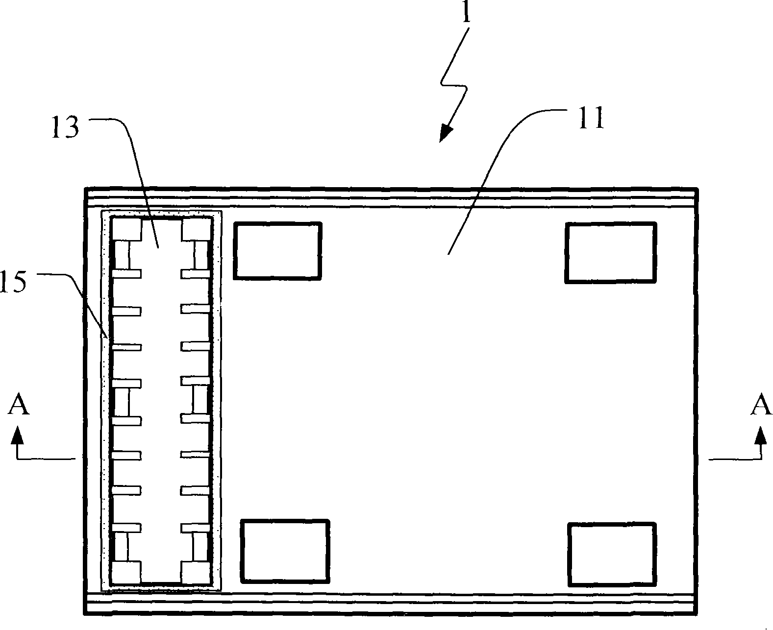
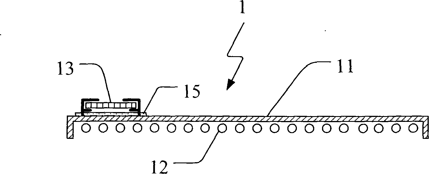
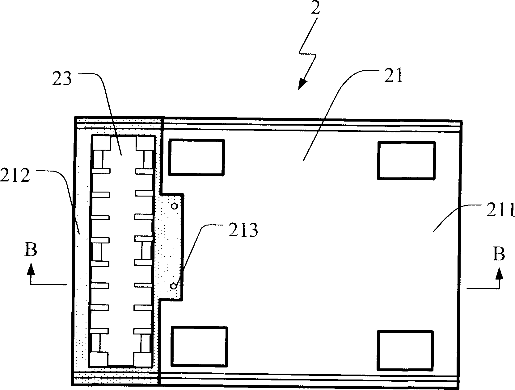
[0022] Please refer to Figure 2A and Figure 2B ,in Figure 2B for along Figure 2A Schematic diagram of the cross-section of the B-B section line. The backlight module 2 of the present invention at least includes a backplane assembly 21 , a light source device 22 and an inverter 23 , wherein the light source device 22 and the inverter 23 are substantially isolated by the backplane assembly 21 . More specifically, in order to improve the shortcomings of existing backlight modules that conduct high heat generated by the light source device to the igniter through the back plate, thereby generating local high temperature and affecting the operation of the igniter, the back plate assembly 21 of the present invention uses different The regions have materials with different thermal conductivity coefficients, so as to isolate the high heat generated by the light source device 22 from being conducted to the lighter 23 and still maintain the heat dissipation of the light source dev...


PUM


Abstract

The invention discloses a backboard assembly used for a backlight module, comprising a first plate body and a second plate body, wherein, side edges of the second plate body are joined with side edges of the first plate body so as to form a substantially continuous plate body; moreover, the heat conduction coefficient of the second plate body is smaller than that of the first plate body, thereby the second plate body can isolate the heat conduction between a light source device and a lighter which are arranged on two opposite sides of the second plate.

Description

technical field [0001] The invention relates to a backplane assembly used for a backlight module of a liquid crystal display; in particular, a backplane assembly helpful for heat conduction. Background technique [0002] Due to the continuous advancement of photoelectric technology and the digitization of image display technology, various displays can be seen everywhere in daily life; among them, liquid crystal displays are widely used in various fields because of their advantages such as high image quality, thinness, low power consumption, and no radiation Among all kinds of electronic products, it has gradually replaced the traditional cathode ray tube display and has become the mainstream in the display market. [0003] Existing direct type backlight modules such as Figure 1A and Figure 1B shown, where Figure 1B for along Figure 1A Schematic cross-sectional view of section line A-A in middle. The backlight module 1 includes a backplane 11 , a light source device 12...

Claims


Application Information

Patent Timeline
IPC IPC(8): G02F1/13357G02F1/133F21V15/06G02F1/1335F21V29/15
Inventor 林明干
Owner AU OPTRONICS CORP
Why Eureka
Try Eureka