A c-band pattern-forming coupled thermal antenna

A technology of pattern and coupled heat, applied in the field of thermal antenna feed, can solve problems such as pattern coverage performance constraints, and achieve the effect of isolating heat conduction

Active Publication Date: 2018-02-09
BEIJING AEROSPACE INST OF THE LONG MARCH VEHICLE +1
View PDF3 Cites 0 Cited by
  • Summary
  • Abstract
  • Description
  • Claims
  • Application Information

AI Technical Summary

Problems solved by technology

In this way, the anti-heat insulation and high temperature resistance performance of the antenna is guaranteed, and the problem that the traditional antenna feeder technology is covered by a thick anti-heat insulation antenna window, and its pattern coverage performance is greatly restricted

Method used


Image

  • A c-band pattern-forming coupled thermal antenna
  • A c-band pattern-forming coupled thermal antenna
  • A c-band pattern-forming coupled thermal antenna

Examples


Embodiment Construction
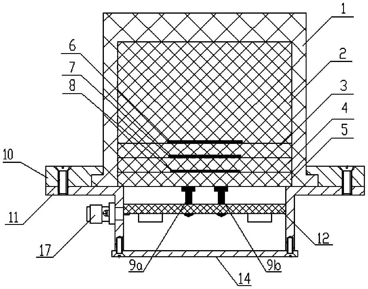
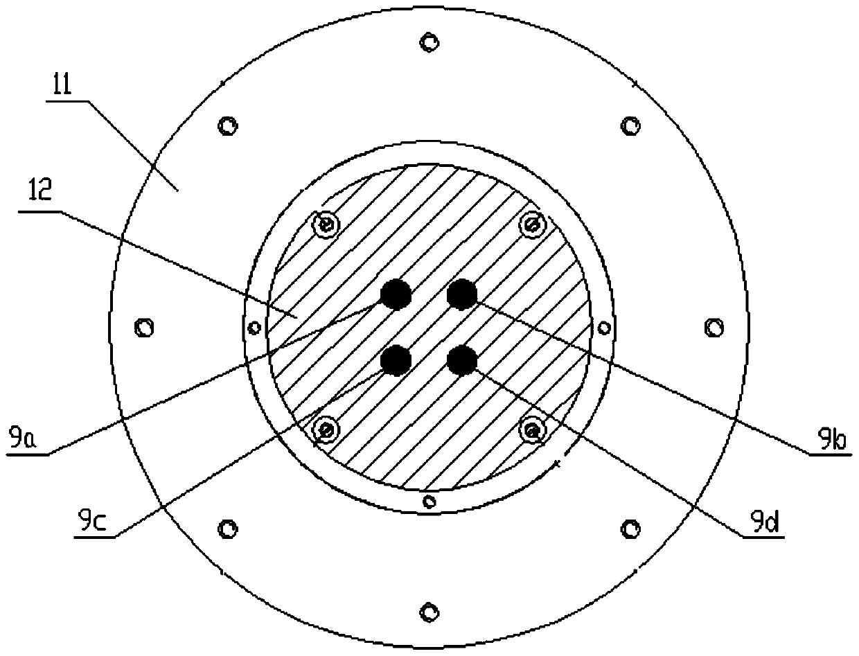
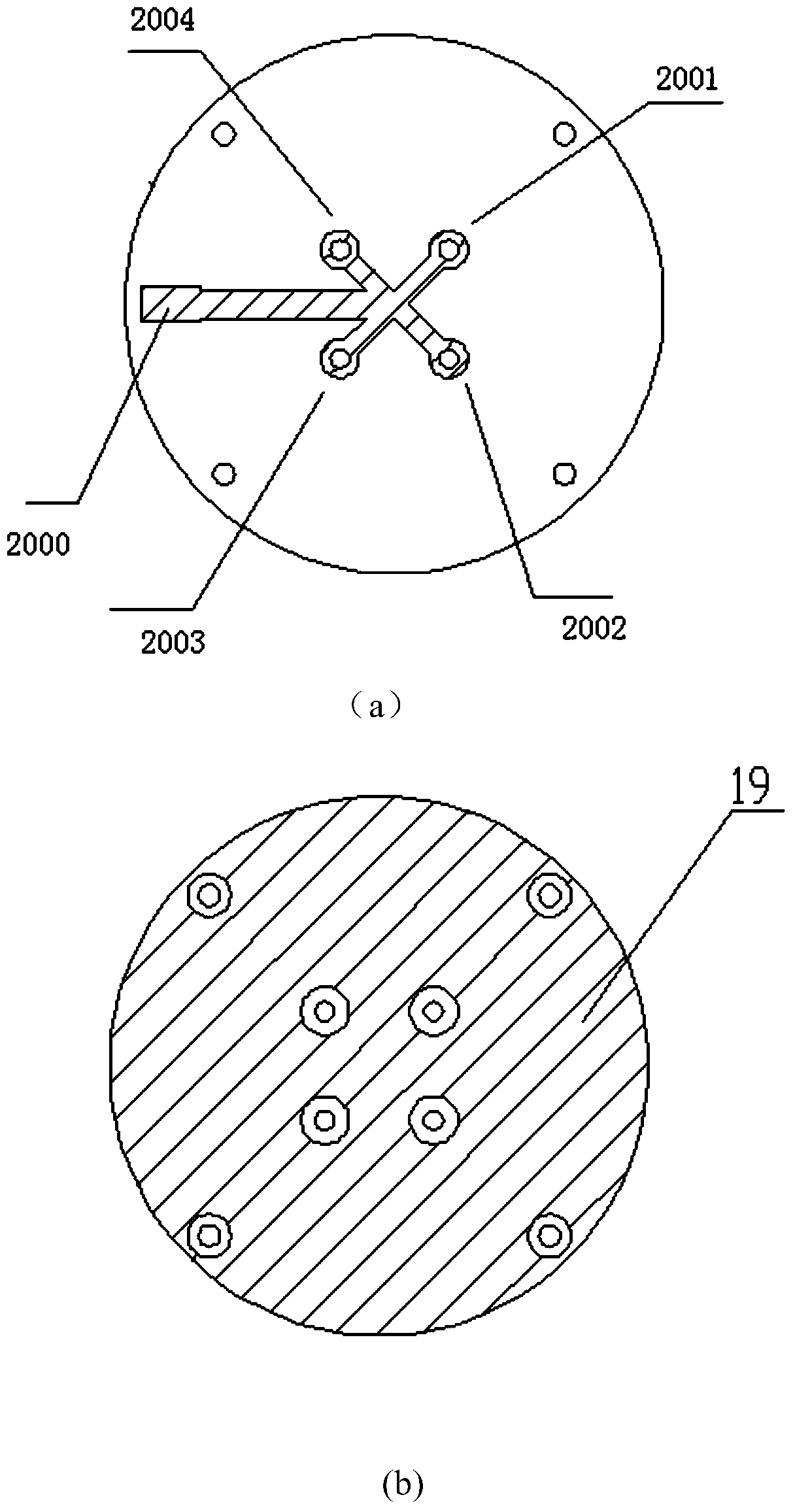
[0043] The basic idea of ​​the present invention is: to propose a C-band pattern-shaped coupling thermal antenna, through the structure design of the multi-layer coupled parasitic radiation unit, the equivalent radiation surface of the antenna is improved, and on the premise of meeting the requirements of the thermal environment, the effective The pattern coverage performance of the antenna is improved; through the feed network design combined with the multi-layer radiation structure design, the antenna pattern is shaped, and the coverage characteristics of the low-elevation angle high-gain pattern that is more in line with the requirements of the measurement and control link are realized; the multi-layer There is no direct metal connection between the coupled parasitic radiation patches, and the substrate of the patch and the antenna insulation material are reused, thus realizing the integrated design of thermoelectricity, which can block the external thermal environment while ...


PUM


Abstract

The invention proposes a C-frequency band directional diagram forming coupling heat antenna. With the structural design of multi-layer coupling parasitic radiation units, equivalent radiation aperture of the antenna is improved, and the directional diagram coverage performance of the antenna is effectively improved on the premise that the requirement of heat environment is met; by a feed network design combined with a design of a multi-layer radiation structure, the directional diagram forming of the antenna is fulfilled, and the coverage characteristics of a low-elevation angle and high-gain directional diagram conformity to the demand of a measurement and control link are achieved; no direct metal connection is arranged among multi-layer coupling parasitic radiation patches, multiplex of a patch substrate and an thermal insulation material of the antenna is realized, and thus, a thermoelectric integrated design is achieved; the antenna radiation requirement is met, and meanwhile, an effect of preventing an external heat environment is achieved. The antenna design can be promoted to the designs of forming heat antennas for measurement and control frequency bands such as L, S, C, X, Ku, Ka and the like, a favorable reference basis is provided for the deigns of the forming heat antennas, and the antenna has strong applicability.

Description

technical field [0001] The invention relates to a C-band pattern-forming coupled thermal antenna, which belongs to the technical field of thermal antenna feed. Background technique [0002] In the field of aircraft measurement and control, the antenna, as the front end of wireless measurement and control, needs to meet the requirements of the thermal environment during the flight of the aircraft and the coverage performance requirements of the measurement and control link for the antenna pattern. Under the coverage of thick anti-heat insulation antenna window, the traditional antenna feed technology's pattern coverage performance is greatly restricted, especially in the low elevation angle range of the antenna, the pattern gain is further reduced, which increases the risk of transmitting and receiving data in the measurement and control link. Contents of the invention [0003] The technical problem solved by the present invention is: to overcome the deficiencies of the pri...

Claims


Application Information

Patent Timeline
Patent Type & Authority Patents(China)
IPC IPC(8): H01Q1/36H01Q1/38H01Q1/50H01Q13/08
Inventor 王威王煊杨博昆谢叶贵李欣冀王健郑颖邝浩欣张鹏陈海英高凯
Owner BEIJING AEROSPACE INST OF THE LONG MARCH VEHICLE
Why Eureka
Try Eureka