Light emitting apparatus

A technology for light-emitting devices and light sources, which is applied to lighting devices, electroluminescent light sources, fixed lighting devices, etc., can solve problems such as inability to maintain conduction and occupancy, and achieve the effect of realizing the structure.

Inactive Publication Date: 2008-08-27
KOITO MFG CO LTD
View PDF1 Cites 38 Cited by
  • Summary
  • Abstract
  • Description
  • Claims
  • Application Information

AI Technical Summary

Problems solved by technology

However, in this method, for example, in order to slow down the conduction speed of the switching element, when the switching element is turned on and off at an on-duty of 10%, there is a concern that there will be a period in which suf

Method used


Image

  • Light emitting apparatus
  • Light emitting apparatus
  • Light emitting apparatus

Examples


Embodiment Construction

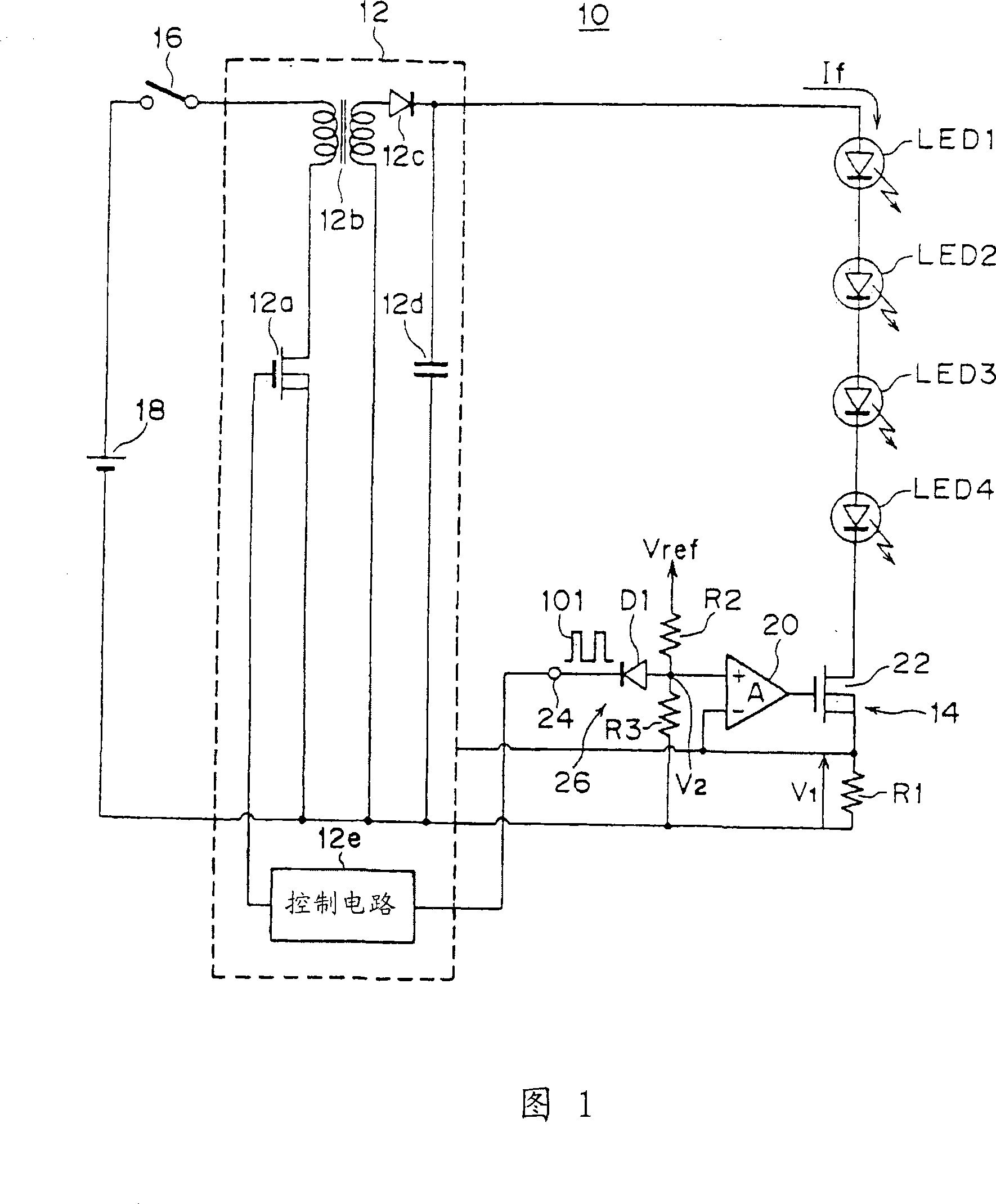
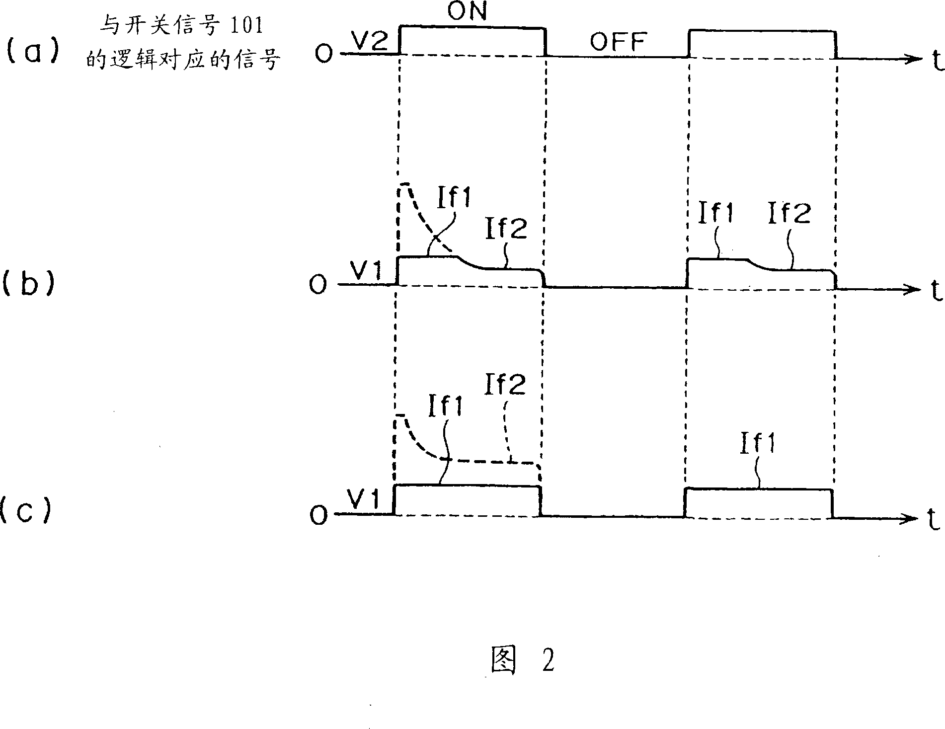
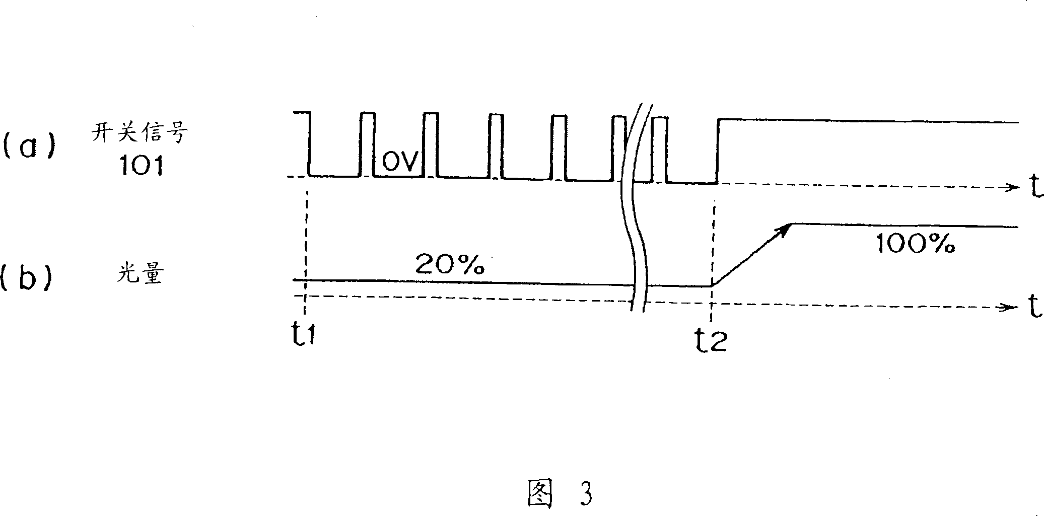
[0045] Hereinafter, an embodiment of the present invention will be described based on the drawings. Fig. 1 is a block diagram showing the light-emitting device of the first embodiment of the present invention; Fig. 2 is a diagram showing the relationship between the signal corresponding to the logic of the first switching signal and the current of the light source, (a) is a diagram related to the first The waveform diagram of the signal corresponding to the logic of the switching signal, (b) is a waveform diagram showing the current waveform of the light source when the DC / DC converter performs feedback control on the current of the light source, (c) is a waveform diagram showing no DC / DC conversion Figure 3 is a diagram showing the state of each part in the first embodiment, (a) is a signal waveform diagram of the switch signal 101, (b) It is a characteristic diagram of the visual light quantity of the whole light-emitting diodes LED1-LED4; FIG. 4 is a block diagram showing t...


PUM


Abstract

The invention provides an illuminating device. The objective of the invention is to inhibit overshoot current flowing over semiconductor light source and hold linear relationship between ON duty of determined light consumption and light consumption amount. In conduction of light emitting diodes LEDs 1 to 4, a switching signal 101 is converted into a voltage V 2 or 0V through a signal converter 26 in accordance with a logic level thereof The voltage obtained by the conversion is compared with a voltage V 1 on both ends of a resistor R 1 through an operational amplifier 20 to open/close an output loop by an NMOS transistor 22, a current If of the light emitting diodes LEDs 1 to 4 is limited to a current If 1 so as not to exceed a maximum current, and a current defined with an ON duty of the switching signal 101 is caused to flow as a mean current to the light emitting diodes LEDs 1 to 4 to inhibit an overshoot current from flowing to the light emitting diodes LEDs 1 to 4 while the output loop is closed.

Description

technical field [0001] The present invention relates to a light emitting device, and more particularly to a light emitting device configured to be usable as a vehicle lamp. Background technique [0002] Conventionally, semiconductor light emitting elements such as LEDs (Light Emitting Diodes) are known as light sources for vehicle lamps. When lighting LEDs and the like, for example, a structure is adopted in which a DC / DC converter is used as a power supply to boost the battery voltage while chopping, rectifies and smoothes the boosted voltage, and Provides smoothed DC power to LEDs. At this time, a shunt resistor is inserted into the output loop of the DC / DC converter in addition to the LED, and the current of the LED is detected from the voltage across the shunt resistor, and feedback control is performed in the DC / DC converter based on the detected current. , so that the current flowing in the LED is constant. When a plurality of LEDs are connected in series, each LED ...

Claims


Application Information

Patent Timeline
IPC IPC(8): H05B37/02H02M3/00F21S8/10F21Y101/02H05B44/00H01L33/00
CPCH05B33/0815H05B33/083H05B45/48H05B45/382
Inventor 伊藤昌康北河孝悦村上健太郎
Owner KOITO MFG CO LTD
Why Eureka
Try Eureka