Concentric ring adverse current type hypergravity swinging bed device
A technology of high-gravity rotating bed and concentric circles, applied in chemical/physical/physical-chemical fixed reactors, dispersed particle separation, fractionation, etc., can solve the problem of large rotor liquid holdup, small rotor liquid holdup, and large pressure drop To achieve the effect of increasing the number of theoretical plates, reducing the pressure drop, and reasonable initial distribution
- Summary
- Abstract
- Description
- Claims
- Application Information
AI Technical Summary
Problems solved by technology
Method used
Image
Examples
Embodiment 1
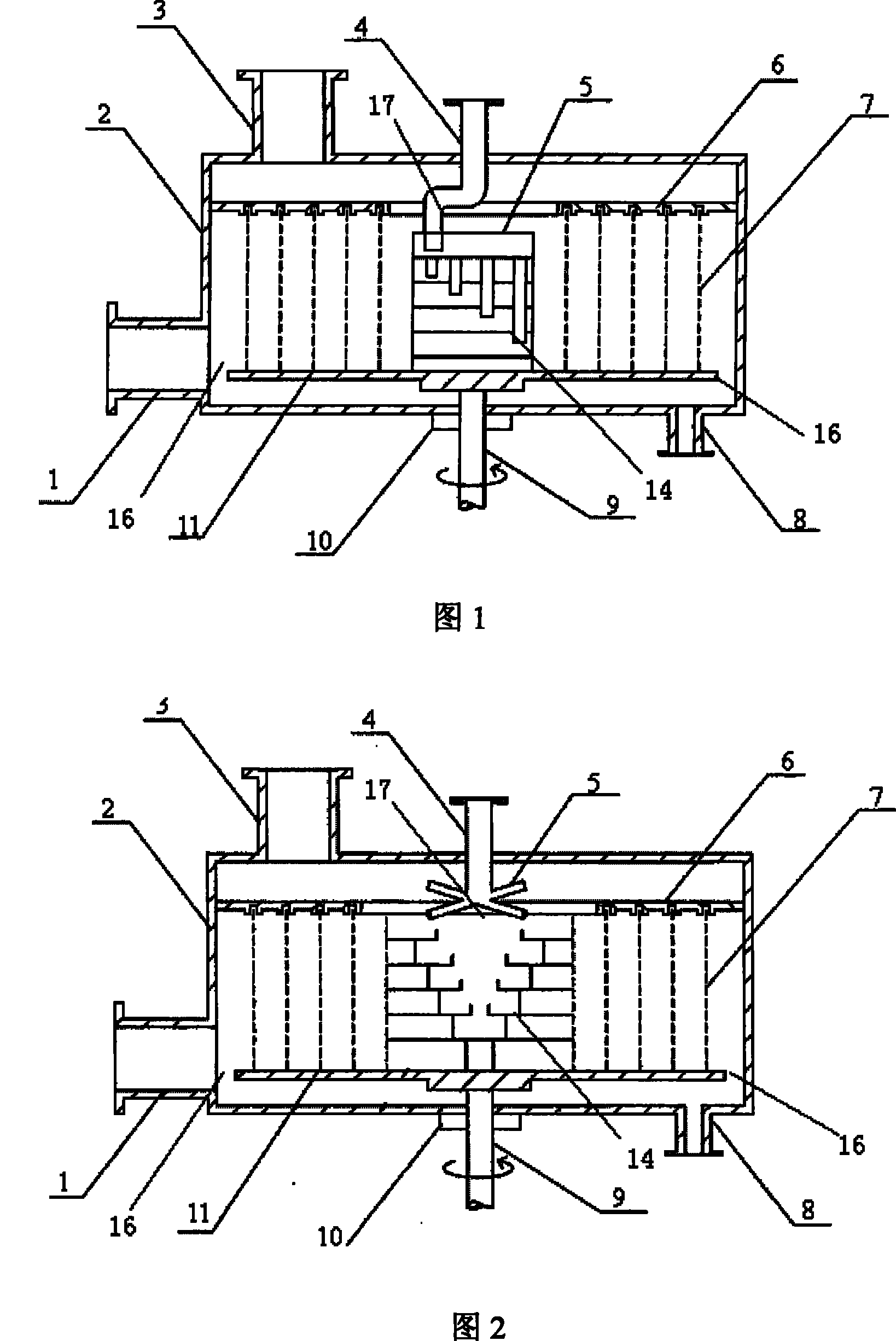
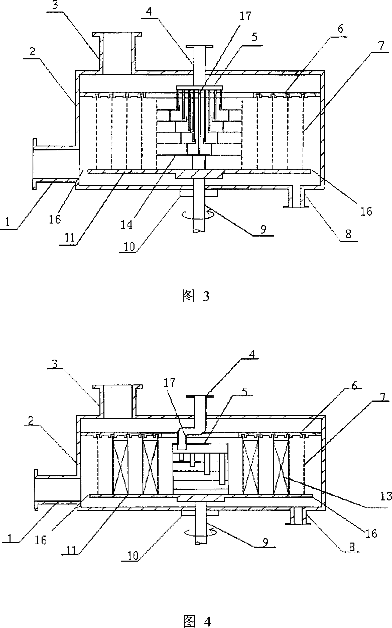
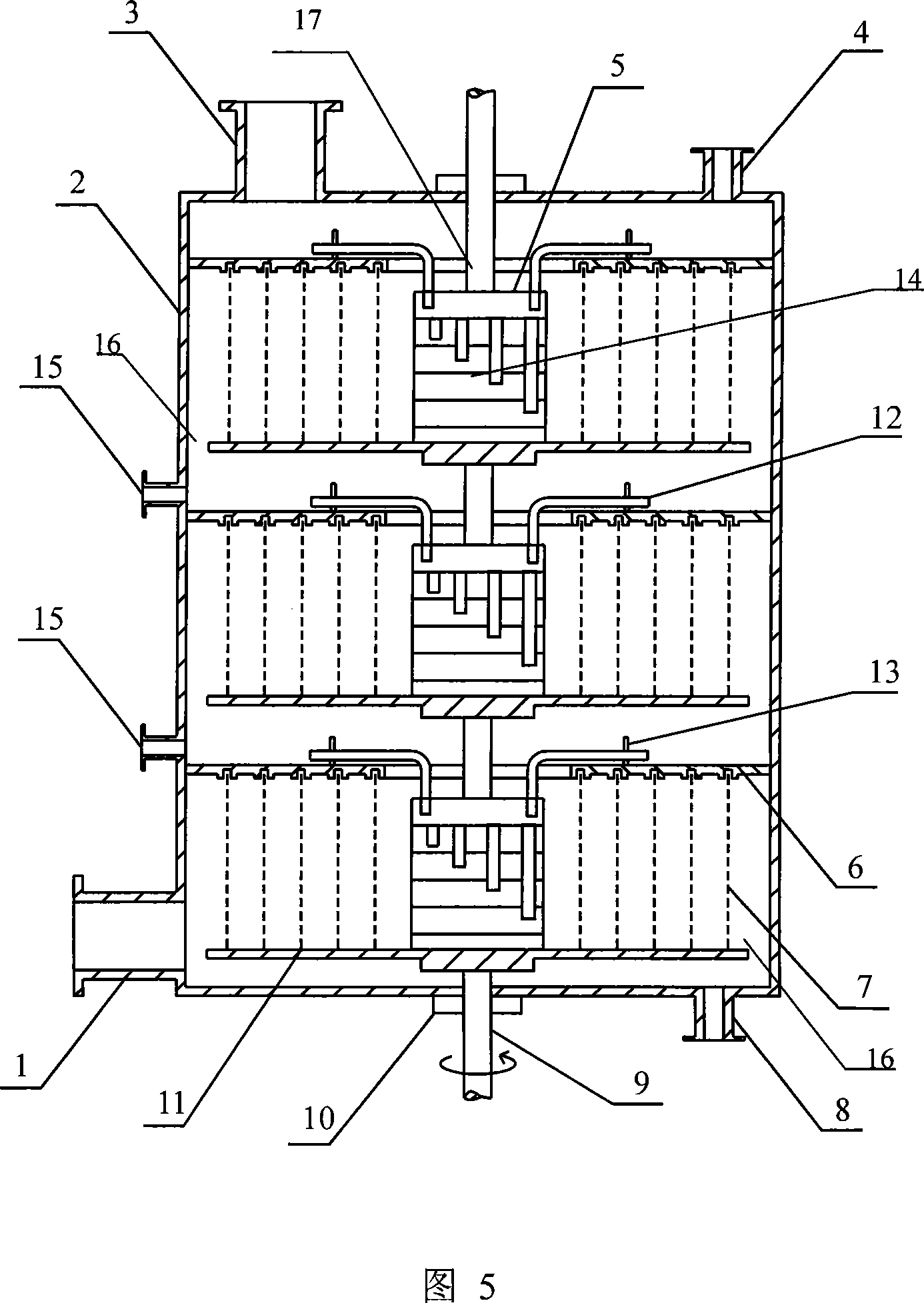
[0020] figure 1 Shown is a single-layer concentric counterflow type supergravity rotating bed device, including a shell 2, a liquid phase inlet 4 and a gas phase outlet 3 are arranged on the upper end of the shell 2, and a gas phase inlet 1 and a liquid phase inlet 1 are arranged on the lower end of the shell 2. The phase outlet 8, the liquid phase inlet 4 is set at the center of the upper end surface of the housing 2, the center of the housing 2 is provided with a rotating body 9, and a rotor is connected to the rotating body 9, and the rotor includes The rotating disc 11 fixedly connected to the rotating body and the stationary disc 6 fixedly connected to the housing 2 are provided with a first passage opening 16 on both sides of the lower end of the rotor, and a second passage opening 17 is provided at the center of the upper end of the rotor. The second channel port 17 communicates with the gas phase outlet 1 and the liquid phase inlet 4, and the first channel port 16 comm...
Embodiment 2
[0027] Such as figure 2 Shown: this embodiment is identical with embodiment 1 except that the liquid distributor is different from embodiment 1.
[0028] This embodiment adopts as figure 2 In the liquid distributor shown, the drainage distributor 5 adopts a cross-shaped drainage tube, and the lower liquid distributor 14 adopts a stepped distributor, and the cross-shaped drainage tube guides the liquid to different heights in the stepped distributor.
Embodiment 3
[0030] Such as image 3 Shown: this embodiment is identical with embodiment 1 except that the liquid distributor is different from embodiment 1.
[0031] This embodiment adopts as image 3 In the liquid distributor shown, the drainage distributor 5 adopts a pipe-type drainage tube, and the lower liquid distributor 14 adopts a ladder-type distributor, and the liquid is led to different heights in the ladder-type distributor by the pipe-type drainage tube .
PUM
 Abstract
Description
Claims
Application Information
 - R&D
- Intellectual Property
- Life Sciences
- Materials
- Tech Scout
- Unparalleled Data Quality
- Higher Quality Content
- 60% Fewer Hallucinations
Browse by: Latest US Patents, China's latest patents, Technical Efficacy Thesaurus, Application Domain, Technology Topic, Popular Technical Reports.
© 2025 PatSnap. All rights reserved.Legal|Privacy policy|Modern Slavery Act Transparency Statement|Sitemap|About US| Contact US: help@patsnap.com


