Blade tip alula of turbine or steam turbine moving-blade

A turbine and steam turbine technology, applied in the direction of machines/engines, mechanical equipment, engine components, etc., can solve the problems of complex flow in cascade passages, increased total loss of impeller machinery, and reduced work, so as to improve the secondary flow field and reduce The effect of small leaf tip leakage and simple structure

Active Publication Date: 2008-09-03
DALIAN MARITIME UNIVERSITY
View PDF0 Cites 22 Cited by
  • Summary
  • Abstract
  • Description
  • Claims
  • Application Information

AI Technical Summary

Problems solved by technology

The blade tip clearance has the following adverse effects: 1) The existence of the blade tip clearance will reduce the actual flow of the working fluid, resulting in a decrease in work near the blade tip, channel blockage, and increased cascade loss; The suction surface of the blade forms the tip leakage vortex, and the interaction between the tip leakage vortex and the channel vortex makes the flow in the cascade channel more complicated, the flow loss increases, and the air outlet angle is changed at the same time; 3) Since the rotor moves relative to the casing wall, Cause the frictional movement of the boundary layer on the casing wall, forming a friction vortex
The three effects brought by the tip clearance all change the di

Method used


Image

  • Blade tip alula of turbine or steam turbine moving-blade
  • Blade tip alula of turbine or steam turbine moving-blade
  • Blade tip alula of turbine or steam turbine moving-blade

Examples


Embodiment Construction

[0014] The present invention is described in further detail below in conjunction with accompanying drawing:

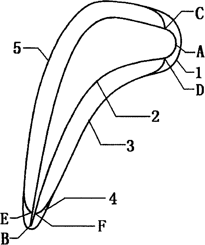
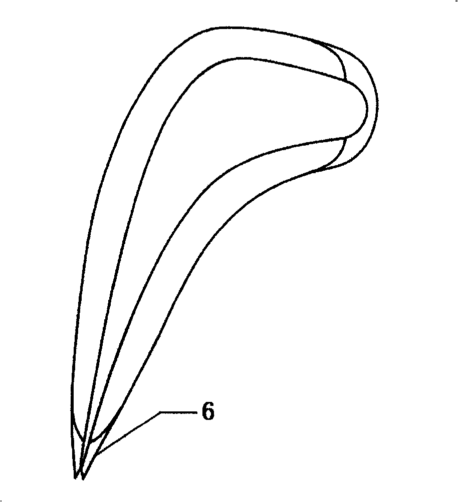
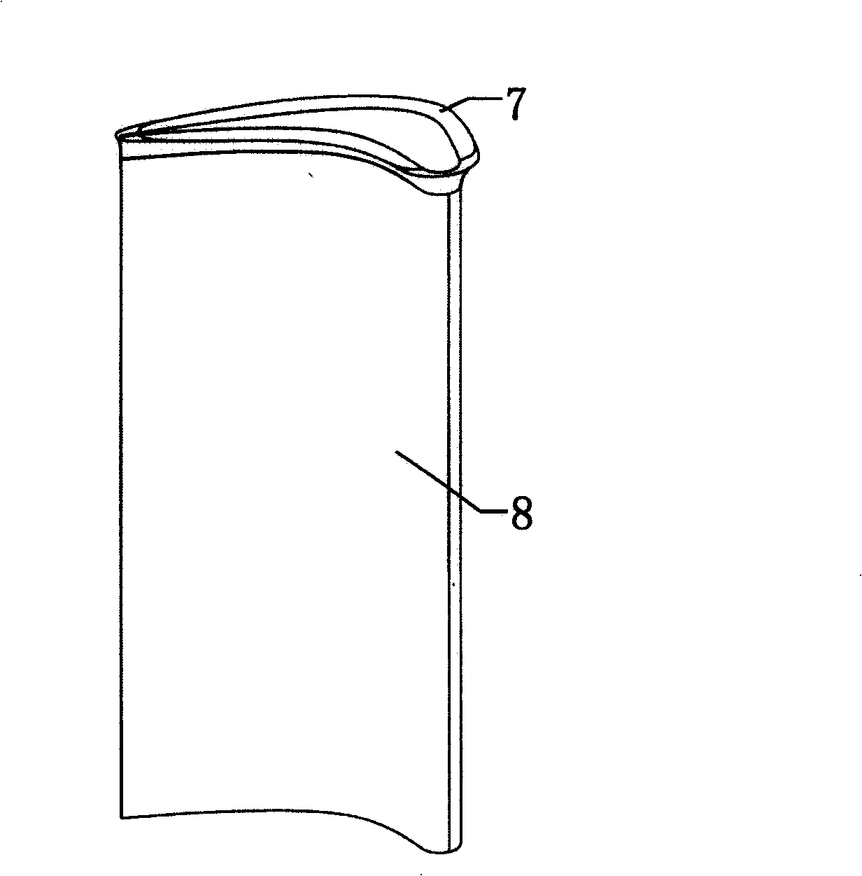
[0015] like Figure 1 to Figure 4 As shown, the turbine or steam turbine moving blade tiplet of the present invention is mainly composed of leading edge wing 1, pressure surface wing 3, suction surface wing 5 and smooth structure trailing edge wing 4 or dovetail structure trailing edge wing 6, and pressure surface wing 3 The suction surface wing 5 is a small airfoil extending in the circumferential direction between the leading edge point A and the trailing edge point B on the basis of the profile of the moving blade, and the pressure surface wing 3 and the suction surface wing 5 The leading edge point D and the leading edge point C are located between the leading edge point A of the rotor blade profile or between the leading edge point A and the maximum thickness of the blade profile, and the trailing edge point F and the trailing edge point E of the pressure surface ...


PUM


Abstract

The present invention provides a tip vane of guided vane of turbine or steam turbine related to field of turbomachine. The tip vane comprises a front edge wing, a pressure surface wing, a suction surface wing and a tail edge wing, the pressure surface wing and the suction surface wing are little vanes expended between front edge point A and tail edge point B of leaf along circumference, front edge point D and C of pressure surface wing and suction surface wing are lied on front edge point A or between front edge point A and most thickness part of guided vane; the tail edge point F and E of the pressure surface wing and the suction surface wing are arranged on tail edge point B or between tail edge point B and the most thickness part of guided vane; the front edge wing and tail edge wing are connected smoothly with the pressure surface wing and suction surface wing, and the front edge wing and the tail edge wing are extended parts of pressure surface wing and suction surface wing at front edge and tail edge. The present invention reduces effect of flow field in channel by tip leakage, tip leakage vortex and scraping gyres, improves cascade flow field, and enhances mechanical efficiency of impeller at the same time.

Description

technical field [0001] The invention relates to the field of turbomachinery, in particular to the design of tiplets applied to moving blades of various turbines or steam turbines. Background technique [0002] In turbomachinery, the geometric dimension of the tip clearance between the tip of the moving blade and the casing is very small compared with the entire flow path, but it affects the flow of nearly 20% of the blade flow path, especially Smaller turbines or steam turbines, etc. The blade tip clearance has the following adverse effects: 1) The existence of the blade tip clearance will reduce the actual flow of the working fluid, resulting in a decrease in work near the blade tip, channel blockage, and increased cascade loss; The suction surface of the blade forms the tip leakage vortex, and the interaction between the tip leakage vortex and the channel vortex makes the flow in the cascade channel more complicated, the flow loss increases, and the air outlet angle is ch...

Claims


Application Information

Patent Timeline
IPC IPC(8): F01D5/14
CPCF01D5/20F01D5/14F01D5/141
Inventor 钟兢军严红明韩吉昂杨凌
Owner DALIAN MARITIME UNIVERSITY
Why Eureka
Try Eureka