Heat treatment device

A technology of heat treatment device and heat treatment chamber, which is applied in the direction of lighting and heating equipment, furnace components, furnace types, etc., and can solve problems such as scratches on glass substrates, difficulties in meeting quality and characteristics, and high quality requirements

Inactive Publication Date: 2010-06-02
PANASONIC CORP
View PDF6 Cites 0 Cited by
  • Summary
  • Abstract
  • Description
  • Claims
  • Application Information

AI Technical Summary

Problems solved by technology

However, in this method, mechanical damage such as scratches caused by contact with the roller table will occur on the glass substrate, and it is difficult to meet the required quality and characteristics.
In particular, the surface of the front panel constituting the display surface within the pair of glass substrates has high quality requirements, and it is difficult to meet the requirements.

Method used


Image

  • Heat treatment device
  • Heat treatment device
  • Heat treatment device

Examples


Embodiment 1

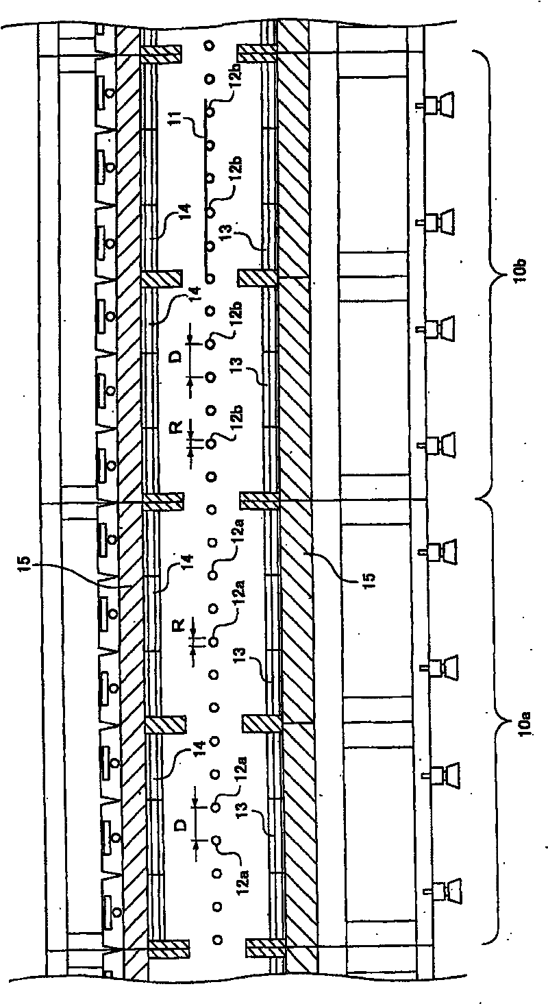
[0036] Using figure 1 and Figure 6 In the heat treatment apparatus with the configuration shown above, the heat treatment conditions are set so that the maximum temperature reaches 600°C using the upper and lower heaters of each heat treatment chamber, and the conveyed glass substrate is heated at 15°C / min as the temperature rise condition to reach the maximum temperature. . The transport speed of the glass substrate was about 15 mm / s.

[0037]The roller table (hereinafter referred to as the first roller table) installed in the heat treatment chamber (hereinafter referred to as the first heat treatment chamber) where the maximum set temperature for heat treatment is less than 250°C is made of silicon carbide as the main component. Sintered body (SiC: about 78% by weight, Al 2 o 3 : about 12 wt%, SiO 2 : about 8% by weight), the length is 1.8m, the outer diameter R is 38mm, and the distance D is 350mm. The proportion of the first heat treatment chamber with a temperature...

Embodiment 2

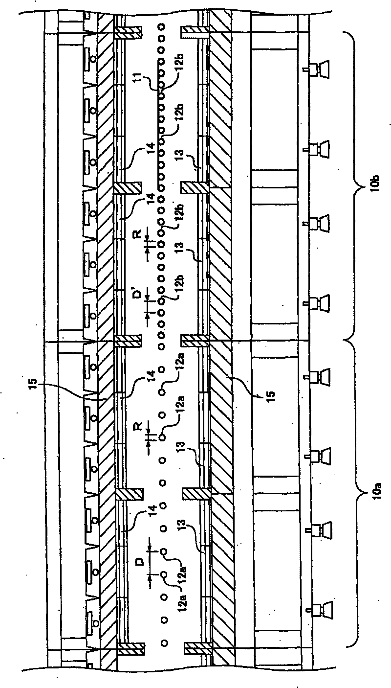
[0047] Using figure 2 and Figure 6 In the heat treatment apparatus having the configuration shown, as in Example 1, the heat treatment conditions were set so that the maximum temperature reached 600° C., and the conveyed glass substrate was heated at 15° C. / min as the temperature rise condition to reach the maximum temperature.

[0048] The first roller table installed in the first heat treatment chamber with a maximum set temperature of less than 250°C is a sintered body mainly composed of silicon carbide, has the same composition as Example 1, has a length of 1.8m, and an outer diameter R is 38mm, install the interval D as 350mm.

[0049] The second roller table installed in the second heat treatment chamber with a maximum set temperature of 250°C or higher is a sintered body mainly composed of mullite, has the same composition as Example 1, has a length of 1.8m, and an outer diameter of R It is 38mm, however, install it with the interval D' as 150mm.

[0050] In this he...


PUM

PropertyMeasurementUnit
densityaaaaaaaaaa
lengthaaaaaaaaaa
Poisson's ratioaaaaaaaaaa

Abstract

In the heat processing device, a plurality heat processing chambers (10a, 10b) for heat processing objects on a glass substrate (11) are connected in a specific direction. Each of the heat processingchambers (10a, 10b) is provided with first and second roll channels (12a, 12b) for placing the glass substrate (11) above for transmitting. The first roll channel (12a) is a roll channel with a vickers hardness increasing with the rise of temperature in the heat processing temperature scope, a second roll channel (12b) is a roll channel with a vickers hardness decreasing with the rise of temperature. Any of the first roll channel (12a) or the first roll channel (12b) is arranged in each of the heat processing chambers (10a, 10b), such that the hardness difference between the vicker hardness thereof and the vicker hardness of the glass substrate at a predetermined temperature of heat processing temperature is small.

Description

technical field [0001] The present invention relates to a heat treatment apparatus used in the manufacture of plasma display panels and the like, and more particularly to a heat treatment apparatus that performs heat treatment while conveying a glass substrate on a roller table. Background technique [0002] Plasma display devices are rapidly spreading because they are becoming larger in size, such as 37 inches to 103 inches, and at the same time their prices continue to fall. The plasma display panel of the plasma display device is configured by regularly arranging electrodes on two flat glass substrates, and at the same time providing a spacer between adjacent electrodes, and separating the two glass substrates (referred to as the front panel and the back panel). ), a plurality of discharge cells separated by spacers are formed, a gas mainly composed of neon is enclosed, and by controlling the voltage applied to each discharge cell, discharge and light emission are selecti...

Claims


Application Information

Patent Timeline
Patent Type & Authority Patents(China)
IPC IPC(8): F27B9/00F27B9/02F27B9/24H01J9/00C03B35/16F27D3/12H01J9/24H01J11/20H01J11/22H01J11/34
CPCY02P40/57H01J9/241H01J11/34H01J2209/3896
Inventor 植松克仁森田真登西木直巳桐原信幸石尾博明
Owner PANASONIC CORP
Why Eureka
Try Eureka