
Working method of lambda seeker

A detector, working technology, applied in the field of lambda detectors

Inactive Publication Date: 2013-07-31
ROBERT BOSCH GMBH
View PDF0 Cites 0 Cited by
  • Summary
  • Abstract
  • Description
  • Claims
  • Application Information

AI Technical Summary

Problems solved by technology

However, in the concentrated exhaust gas, since the water contained in the exhaust gas is decomposed at the cathode, a positive pump current is also generated. Although the applied pump voltage is obviously lower than the electrolysis voltage of water, due to the presence of hydrogen in the exhaust gas, the energy of water decomposition becomes possible, this is due to the generation of water at the counter electrode, the anode

Method used


Image

  • Working method of lambda seeker
  • Working method of lambda seeker
  • Working method of lambda seeker

Examples


Embodiment Construction

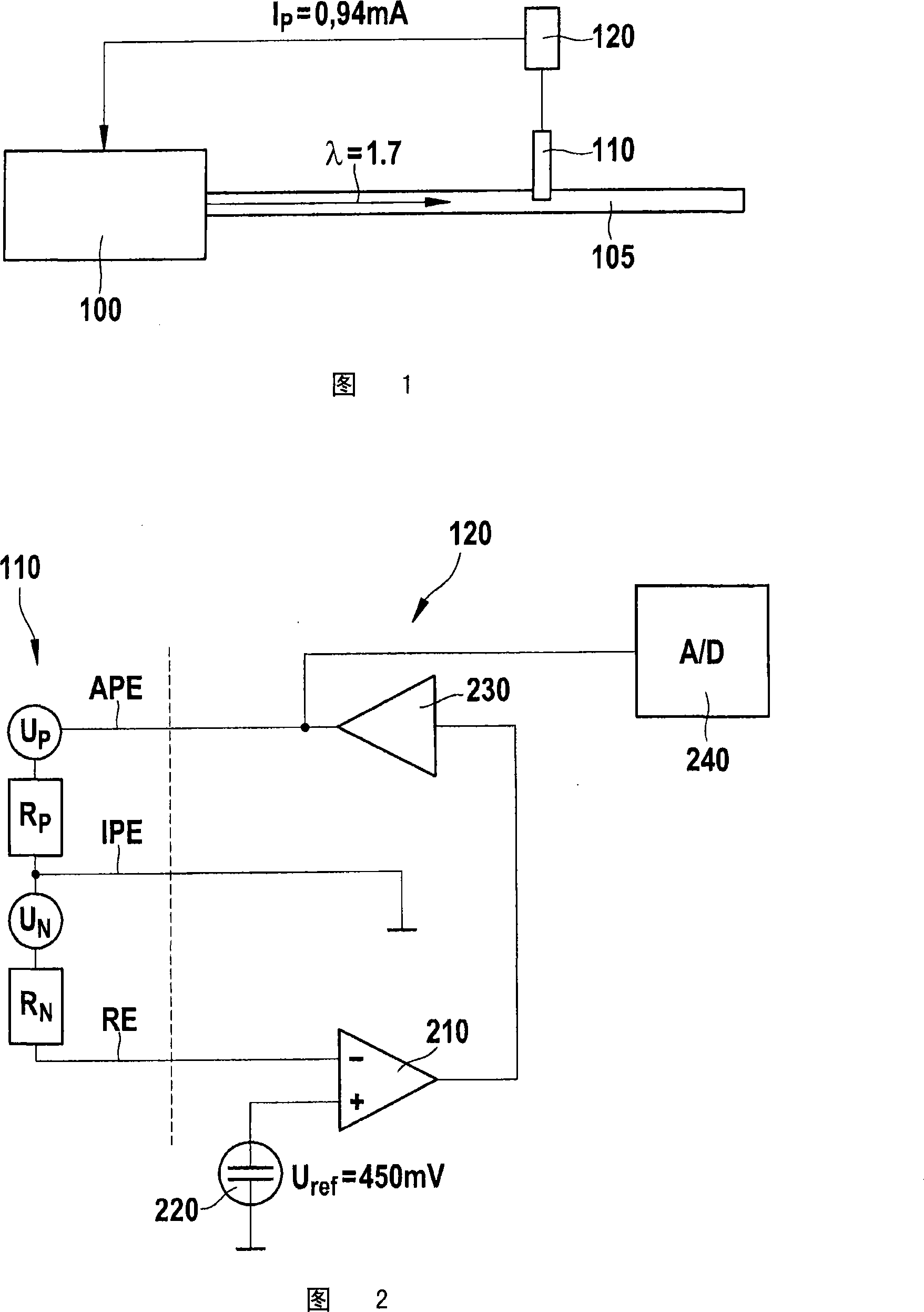
[0026] FIG. 1 shows a schematic diagram of a control system for parameters characterizing the injection process of an internal combustion engine.

[0027] A lambda sensor 110 is arranged in the exhaust tract 105 of the internal combustion engine 100 , the output signal of which is processed in an electronic control unit 120 , in particular an engine control unit.

[0028] For example, at a λ value of λ=1.7 to be adjusted, the electronic control unit 120 predetermines a predeterminable pump current I of, for example, 0.94 mA by means of a characteristic curve stored in a software. P As an adjustment theoretical value for engine fuel injection.

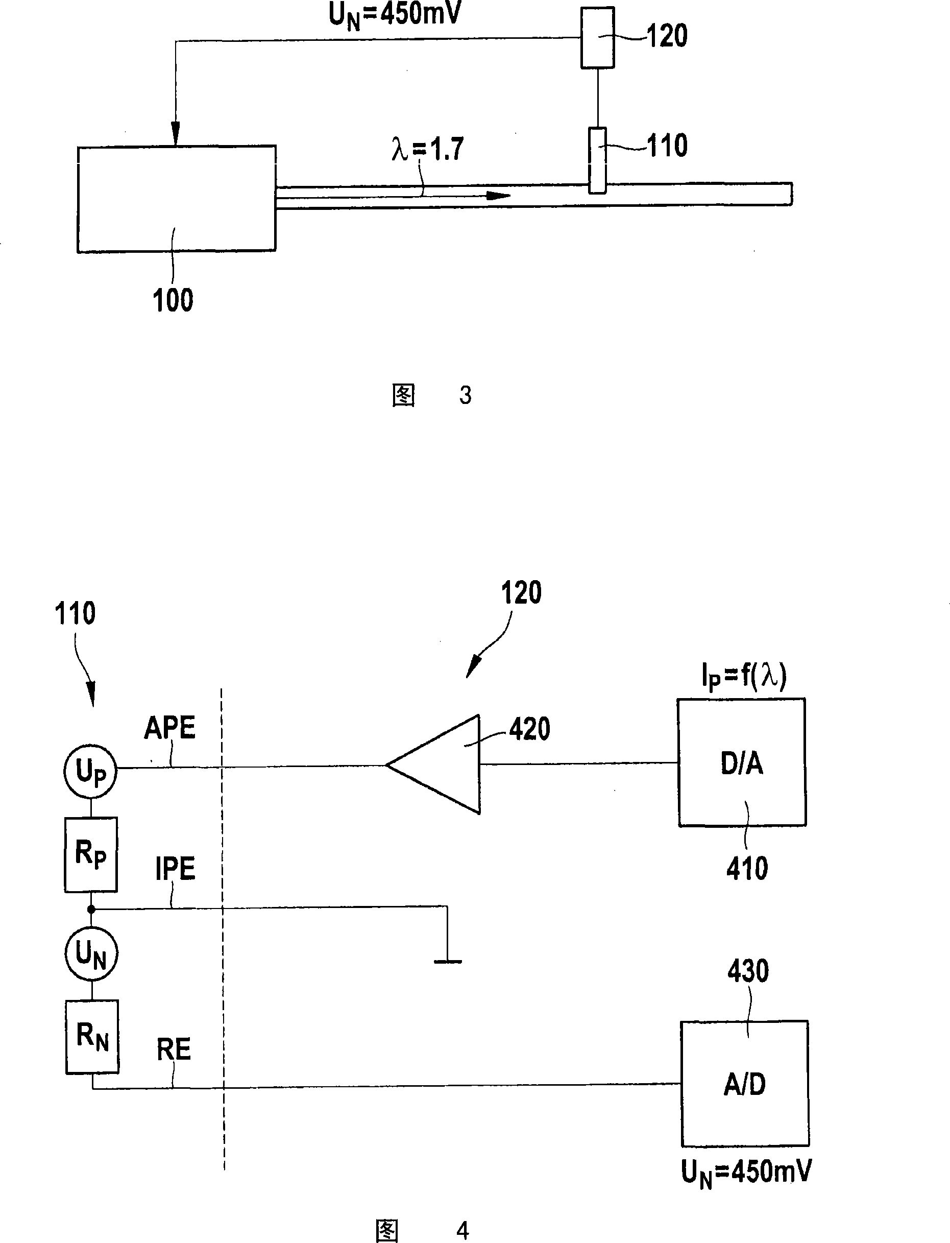
[0029] The lambda probe 110 shown in FIG. 2 consisting of a double cell has an outer pump electrode APE, an inner pump electrode IPE and a reference electrode RE. There is a pump voltage U between the outer pump electrode APE and the inner pump electrode IPE P , there is a Nernst voltage U between the internal pump electrode IPE, whic...


PUM


Abstract

The method involves forming a pump cell with two electrodes which act as pump electrodes, and two electrodes acting as nernst electrode and reference electrode forming a nernst cell. The variables of the internal combustion engine (100) varies the injection process characteristics, such that the nernst voltage (U-N) receives a predetermined value. The nernst voltage is tapped between the electrodes acting as nerst electrode and reference electrode.

Description

technical field [0001] The invention relates to a method for operating a lambda sensor for determining gas components in the exhaust gas of an internal combustion engine. Background technique [0002] Air coefficients are often determined with so-called broadband lambda probes. Such detectors essentially consist of a conventional concentration detector (Nernst detector) acting as an induction cell (galvanische Zelle) and a limiting current cell or "pump" cell. Only an external voltage is applied to this pump cell of the same type as known concentration cells. If this voltage is large enough, a "limiting current" is generated that is proportional to the oxygen concentration on the cathode side of the detector. With this current—depending on the polarity—the oxygen atoms are transported. An electronic regulation circuit is used to supply enough oxygen from the exhaust gas through a very narrow diffusion gap to always accurately supply the concentration detector to maintain ...

Claims


Application Information

Patent Timeline
Patent Type & Authority Patents(China)
IPC IPC(8): G01N27/407F02D41/14F01N11/00
CPCF02D41/1456G01N27/419
Inventor L·迪尔T·塞勒
Owner ROBERT BOSCH GMBH
Learn More