Eureka AIR delivers breakthrough ideas for toughest innovation challenges, trusted by R&D personnel around the world.

Method for recognition of bump-scrape fault of rotor

A fault identification and rotor technology, which is applied in special data processing applications, complex mathematical operations, measuring devices, etc., can solve problems such as decomposition frequency band overlap, and achieve the effects of improving accuracy, high calculation precision, and ease of use

Inactive Publication Date: 2010-06-09
NORTHWESTERN POLYTECHNICAL UNIV
View PDF2 Cites 0 Cited by
  • Summary
  • Abstract
  • Description
  • Claims
  • Application Information

AI Technical Summary

Problems solved by technology

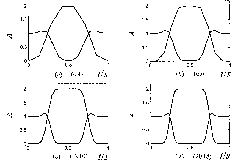
[0004] In order to overcome the shortcomings of the prior art in the problem of overlapping frequency bands, the present invention provides a rotor rubbing fault identification method, which selects a second-generation wavelet predictor and updater that adaptively matches the signal characteristics, eliminating the need for each Decompose irrelevant frequency components in other frequency bands in the frequency band to extract subharmonics that characterize rotor rubbing faults

Method used


Image

  • Method for recognition of bump-scrape fault of rotor
  • Method for recognition of bump-scrape fault of rotor
  • Method for recognition of bump-scrape fault of rotor

Examples


Embodiment 1

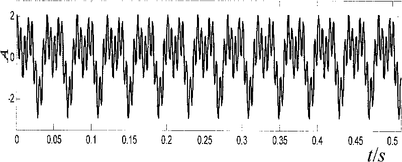
[0039] This embodiment mainly simulates and verifies the correctness of the method of the present invention to decompose the frequency band separation signal, and constructs a simulation signal x(t) composed of three harmonics to simulate the fundamental frequency and its multiple of the vibration signal when the rotor system has a rubbing fault. Frequency components:

[0040] x(t)=sin(2πf 1 t)+sin(2πf 2 t+0.5π)+sin(2πf 3 t)

[0041] The frequencies of the harmonic signal components in x(t) are respectively f 1 = 25Hz, f 2 = 50Hz, f 3 = 200Hz. X(t) is discretized and sampled with a sampling frequency of 2000Hz, and the data length is 1024.

[0042] Step 1: Calculate the second-generation wavelet predictor and updater

[0043] The second generation wavelet predictor P=[p(1), p(2), p(3), ..., p(N)] and updater N and are the number of predictor and updater coefficients, respectively, N ∈ Z, and The calculation method is as follows:

[0044] P is obtained by

[0...

Embodiment 2

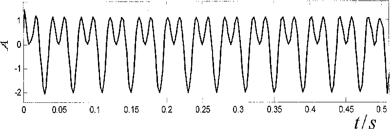
[0081] This embodiment mainly verifies the correctness of engineering fault diagnosis of the method of the present invention. A 50MW turbogenerator set in a thermal power plant consists of a high-pressure cylinder, a low-pressure cylinder, a generator and an exciter. The rated speed of the unit is 3046.8r / min, that is, the power frequency is 50.78Hz. After the unit was overhauled once, it was found that the bearing bush of the high-pressure cylinder vibrated a lot when it was put into operation. In order to find out the cause of the failure, the vibration signal is collected at a sampling frequency of 2000Hz in the vertical direction of the bearing bush of the high-pressure cylinder 2#, and the data length is 1024.

[0082] Step 1: Calculate the second-generation wavelet predictor and updater

[0083] The second generation wavelet predictor P=[p(1), p(2), p(3), ..., p(N)] and updater N and are the number of predictor and updater coefficients, respectively, N ∈ Z, and ...


PUM


Abstract

The invention discloses a method for recognizing rotor rub-impact failure, which comprises using a kurtosis size of a rotor vibration signal as an objective function, selecting a second era wavelet predictor and a renovator in feature of self-adaptable matching rotor vibration signal to decompose the rotor signal; afterconditioning the decomposed rotor vibration signal with each frequency band byusing fourier transform method to eliminate irrelevant frequency and extract hypo-harmonic in order to recognize the impact severe degree of the rotor. The invention excellently solves the problem decomposing frequency band overlapping of the second era wavelet, improves the accuracy for recognizing rotor rub-impact failure, and provides effective practical new technology for electromechanical device failure recognition; the invention is simple, reliable and suitable for engineering practice.

Description

1. Technical field [0001] The invention belongs to the field of electromechanical technology, and in particular relates to a method for identifying early faults of equipment. 2. Background technology [0002] Large-scale electromechanical equipment, such as generator sets, aero engines, etc., in harsh environments such as high speed, heavy load and strong impact, its core component, the rotor, is prone to rubbing faults. The rubbing fault signal is very weak at the initial stage, and the fault contained in the signal The characteristic information is in different frequency bands and is overwhelmed by vibrations and a lot of random noise caused by other moving parts. Therefore, how to identify the characteristics of rubbing faults in different frequency bands from weak signals or rotor vibration signals that have been submerged by noise is the key to accurately identify rotor rubbing faults. With its good time-frequency localization characteristics, wavelet transform can rea...

Claims


Application Information

Patent Timeline
Patent Type & Authority Patents(China)
IPC IPC(8): G06F17/00G06F17/14G01M19/00G01M99/00
Inventor 姜洪开王仲生李华星田红波
Owner NORTHWESTERN POLYTECHNICAL UNIV
Why Eureka
Eureka Blog
Learn More