Method for detecting signal twitter based on time-frequency domain analysis

A detection method and technology in the frequency domain, applied in the direction of using signal quality detectors for error detection/prevention, correct operation testing, digital transmission systems, etc. Transient jitter and other issues

Inactive Publication Date: 2008-09-03
吴伟
View PDF0 Cites 7 Cited by
  • Summary
  • Abstract
  • Description
  • Claims
  • Application Information

AI Technical Summary

Problems solved by technology

Unfortunately, the existing jitter spectrum analysis technology loses all the time information in the process of applying Fourier transform to transform the time trend waveform of jitter from the time domain to the frequency domain, so what is obtained is the statistical value of the frequency component , it is impossible to characterize the time-varying process of the jitter frequency component
In addition, in addition to the above-mentioned steady-state modulation of signal frequency and phase, when electronic equipment is used in various complex application environments, it often encounters random interference, which may cause transient modulation of signal frequency and phase. signal transient jitter
Sometimes the instability of the signal circuit itself will also cause the transient jitter of the signal
In the existing frequency spectrum analysis of jitter, its Fourier transform assumes that the analyzed signal is a periodic signal, so it is impossible to diagnose the transient jitter of the signal

Method used


Image

  • Method for detecting signal twitter based on time-frequency domain analysis
  • Method for detecting signal twitter based on time-frequency domain analysis
  • Method for detecting signal twitter based on time-frequency domain analysis

Examples


Embodiment 1

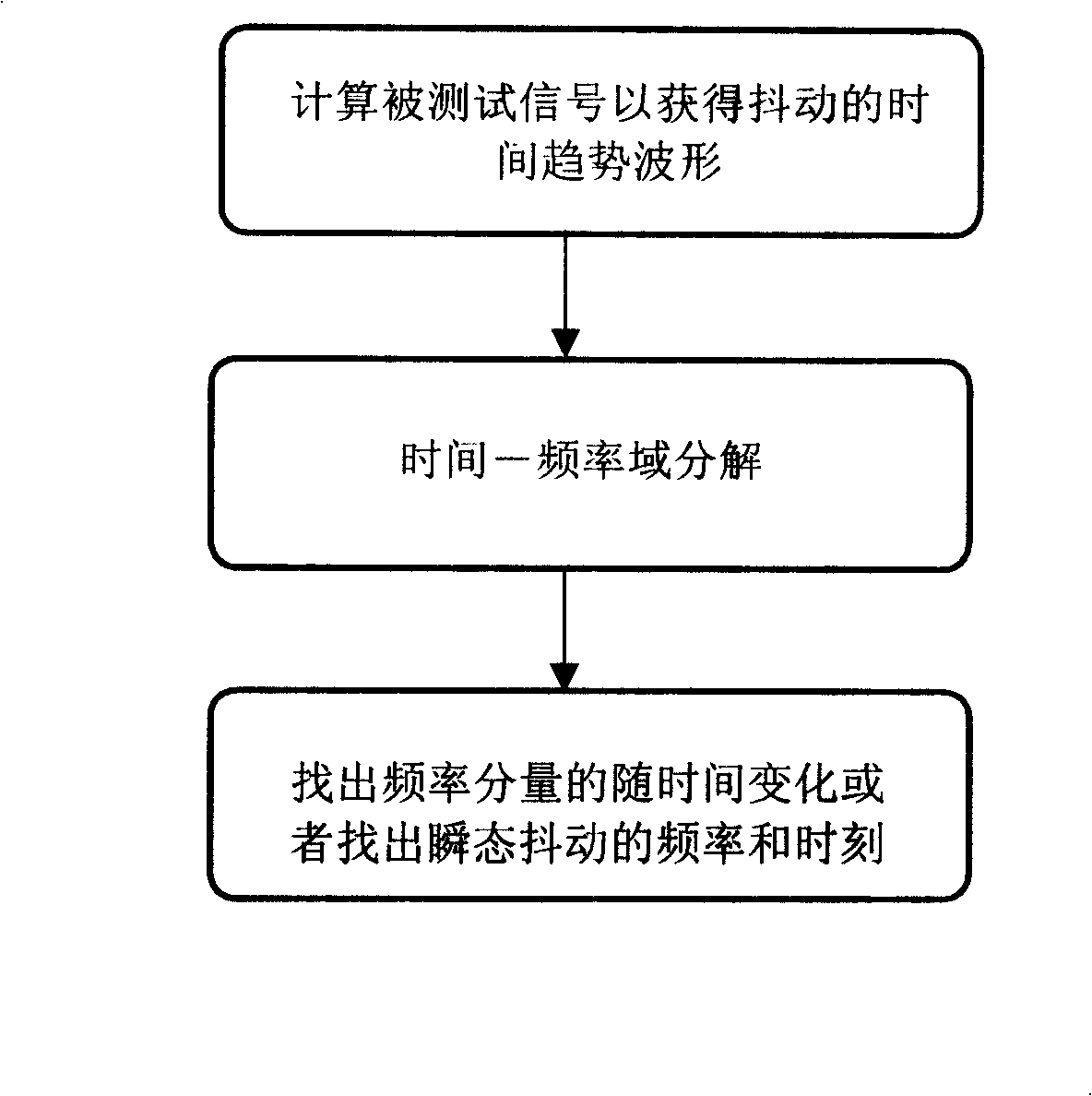
[0025] Embodiment 1: This embodiment discloses that the frequency components of signal jitter change with time. Such as figure 1 Shown in, the concrete method step of the present invention is:

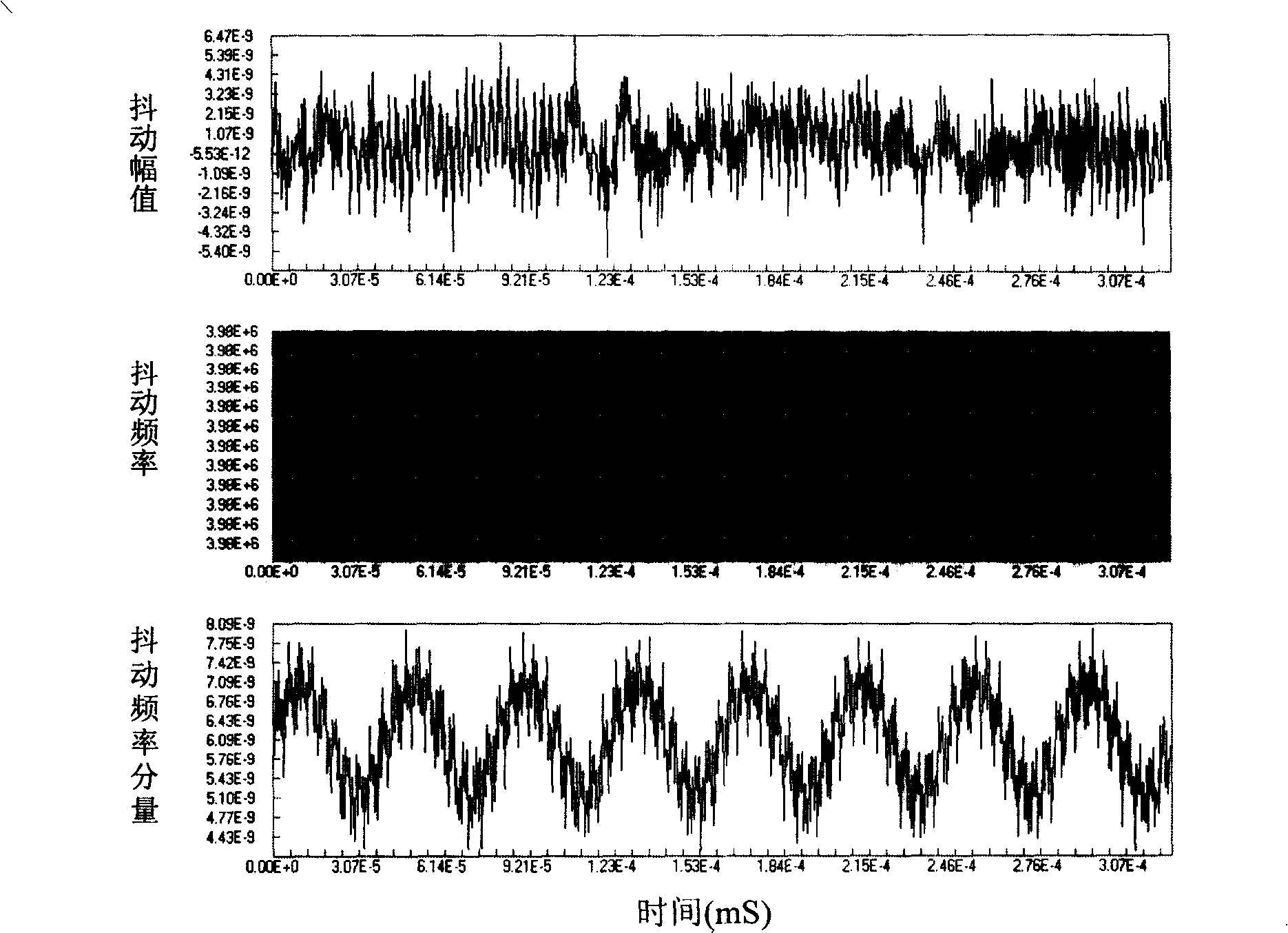
[0026] Calculate the time trend waveform of the signal under test to obtain its jitter. Various jitter calculation methods whose calculation results can be represented by a time trend are available. In the present embodiment, the detected signal is the clock signal of a certain digital switching equipment, which is recorded and calculated by a digital oscilloscope, and its time interval jitter (TIE) is obtained as follows: figure 2 The TIE time trend waveform of the clock signal shown above. Those skilled in the art know that there are many oscilloscope products with jitter testing, which can measure and record the signal under test and calculate its jitter time trend waveform.

[0027] Decompose the TIE time trend waveform into the time-frequency domain. Converting time domain...

Embodiment 2

[0046] Embodiment 2: This embodiment discloses the time and frequency at which transient jitter occurs. also in accordance with figure 1 The specific steps:

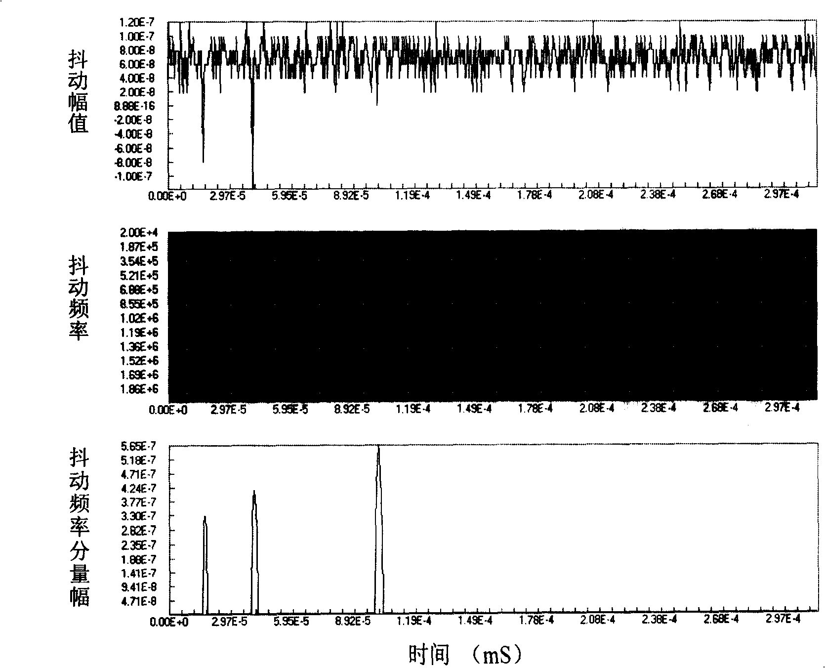
[0047] Transform the signal under test into a time trend waveform of jitter. Tested data is the serial data signal of certain digital exchange equipment in the present embodiment, is detected and recorded by digital oscilloscope and calculates its period jitter (PJ), obtains as follows image 3 The data signal PJ time trend waveform shown in the figure above.

[0048] Decompose the PJ time trend waveform of the data signal into the time-frequency domain. It is realized by formula (2) wavelet transform or formula (3) short-time Fourier transform. In this embodiment, wavelet transform is adopted.

[0049] The result of wavelet transform is in two-dimensional image image 3 Chinese chart description. Here the Y-axis shows frequency components from 0.02MHz to 2MHz in order to include the frequency range where tran...


PUM


Abstract

A detecting method of signal shaking is provided, which analyzes time-frequency field of the time trend wave shape of the signal shaking to disclose frequency component time varying and detect the transient state shaking. The method comprises following steps: firstly, converting the detected signals to the shaking time trend wave shape, then dividing the shaking time trend wave shape in the time-frequency field and finding out the time varying of the shaking frequency component or finding out the frequency of the transient state shaking and the occuring moment.

Description

technical field [0001] The invention relates to a signal jitter measurement method, in particular to a signal jitter detection method based on time-frequency domain analysis. Background technique [0002] Jitter (JITTER) is a well-known term in the art, which is defined as the time deviation of the position of a signal edge from its ideal position, and is often called timing distortion. Jitter is caused by heat, electromagnetic noise, circuit instability, transmission loss, and ambient interference. Jitter can cause data transmission errors in the data transmission system, thereby reducing the overall reliability of the system. [0003] Jitter can be divided into random jitter and quantitative jitter. Random jitter is essentially a Gaussian distribution, generally caused by factors such as thermal noise and shot noise, and has a power spectral density, which is a function of power. Quantitative jitter includes the following components: periodic jitter (Period Jitter, PJ),...

Claims


Application Information

Patent Timeline
Patent Type & Authority Applications(China)
IPC IPC(8): H04L1/24H04L1/20
CPCH04L1/205
Inventor 吴伟
Owner 吴伟
Why Eureka
Try Eureka