Metal rope helmet machining process and matching die

A processing technology, metal rope technology, used in the bundling of ends, textiles and papermaking, textile cables, etc., can solve the problems of textile or human injury, uneven pressure, damage to the protective coating on the outer surface, etc., to achieve the overall shape Intact, reduced production costs, sleek and full appearance

Active Publication Date: 2008-09-10
LONGJIN FUSHI SHANGHAI
View PDF2 Cites 7 Cited by
  • Summary
  • Abstract
  • Description
  • Claims
  • Application Information

AI Technical Summary

Problems solved by technology

Such a shoelace headgear is easy to cause damage to textiles and human body (including workers in processing and production) due to the large convex plate of the opening, or produces sharp corners due to uneven strength after stamping, resulting in damage to textiles or human body.
[0007] At present, the stamping dies on the shoelaces that the shoelace headgear is fixed are generally upper and lower split molds (see Figure 5 ), the pressure given is not uniform, and it is easy to cause the rope pulley after processing to loosen or even fall off
In addition, the semi-cylindrical opening metal sleeve in the past has barbs when it is a semi-finished product. During processing, under the pressure of the upper and lower split molds, it is easy to make the barbs under the pressure and flatten the barbs, making it difficult to fix the rope. Loosening or even falling off of the rope pulley
In the past, during the stamping movement of the upper and lower split molds, the stroke distance between the upper and lower parts was relatively large, and the contact area between the metal headgear and the metal headgear was large under the stamping of the mold, which easily caused wear and scratches on the outside of the metal headgear, and easily produced Defects such as deformation, plating on the outer surface and damage to the protective coating
[0008] In addition, the installation process of this upper and lower split mold is relatively complicated, and it takes a long time to fix and debug the upper and lower parts at the same time before it can be used. Damaged and deformed
The more serious problem is to use this kind of upper and lower split molds. When workers process the ropes, they must hold the ropes and put them into the lower mold and step on the stamping switch to make the upper mold stamp it. At this time, the workers' hands cannot Leaving the rope, it needs to be stable and coordinated, so the possible danger to the stamped upper mold is huge

Method used


Image

  • Metal rope helmet machining process and matching die
  • Metal rope helmet machining process and matching die
  • Metal rope helmet machining process and matching die

Examples


Embodiment Construction

[0051] The present invention will be further described below in conjunction with the accompanying drawings and specific embodiments.

[0052] see Figure 9 , the metal rope headgear processing technology includes the following steps:

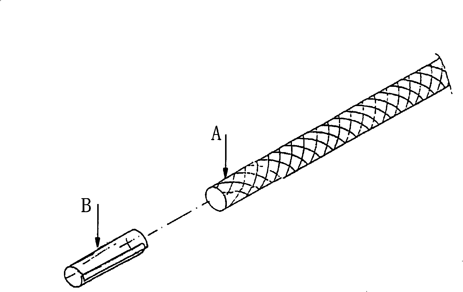
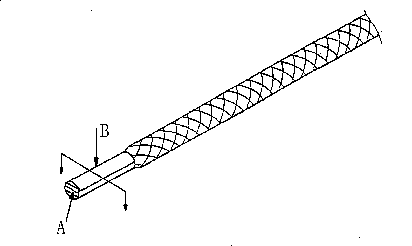
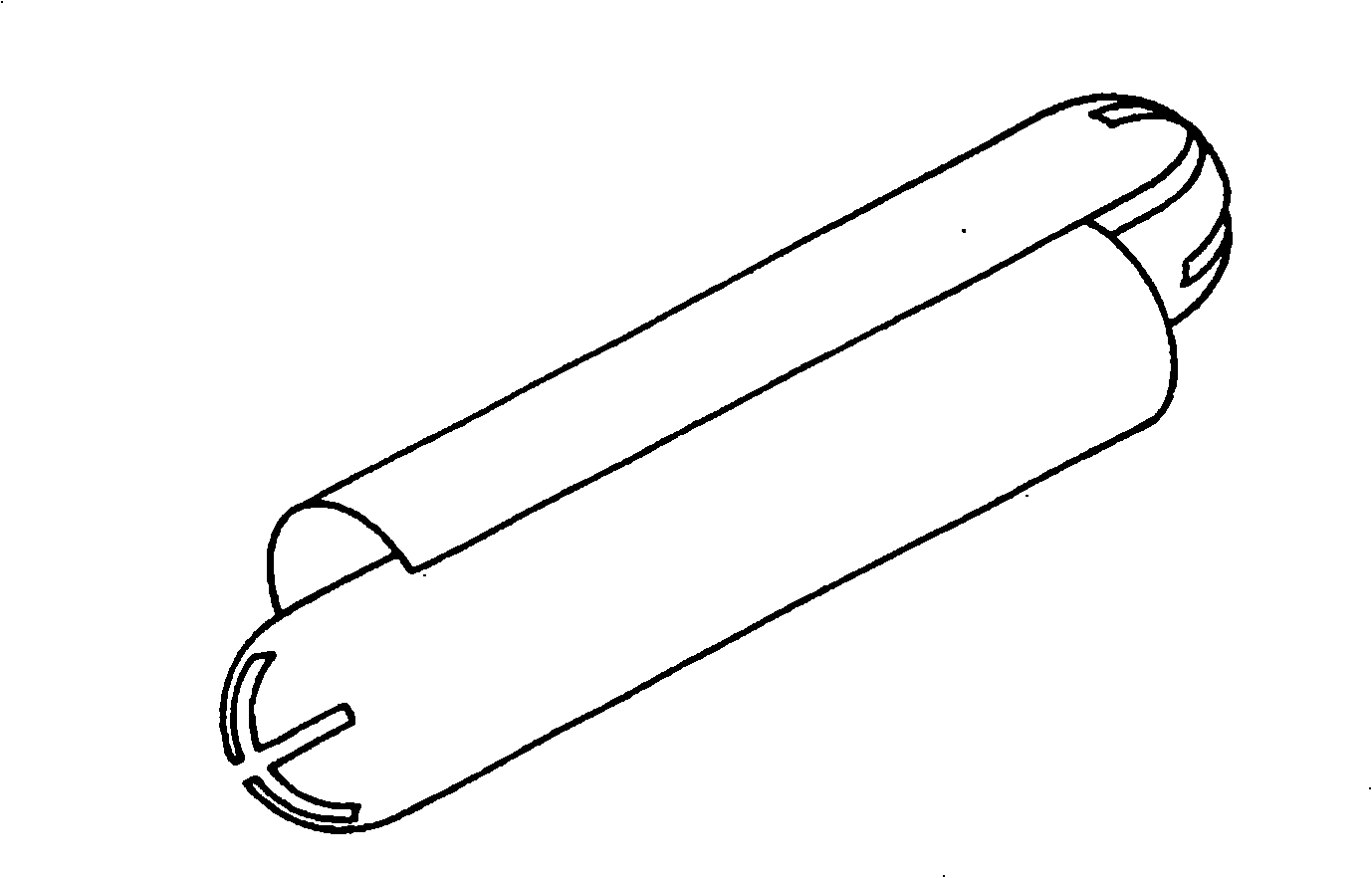
[0053] 1. Using conventional technology, use copper to process a metal headgear 1, so as to pass through the sensitive needle detector. See Figure 6, Figure 7 and Figure 8 The shape of the metal headgear 1 is cylindrical, with a hemispherical 11 at one end and a circular opening 12 at the other end. There is a trident suture 13 at the hemispherical 11, and a side suture 14 at the side edge. The sutures 14 are connected and communicated with both ends of the metal headgear 1; of course, the metal headgear 1 can also be in other shapes, such as a cylindrical shape. What kind of conventional process is used is well known to those skilled in the art, and will not be described in detail here.

[0054] 2. Process the film-type rope head 3 on th...


PUM


Abstract

The invention discloses a metal rope with a headgear processing technique, comprising the following steps that: 1. a cylindrical metal headgear is processed by the conventional technique, one end of the metal headgear is semiglobular, the other end has a circular opening, the semiglobular position is provided with a plurality of joint marks, a lateral edge is provided with a lateral joint mark which is connected and communicated with the two ends of the metal headgear; 2. a film type rope belt head is machined on a rope belt by adopting the conventional technique; 3. the film type rope belt head on the rope belt is inserted into the circular opening at one end of the metal headgear, the film type rope belt head and the metal headgear are inserted into a jointed synthesized matched die, a press machine is started, a plurality of punching thorns arranged on the die are stung into the metal headgear and the film type rope belt head at the same time to form reversed thorns to ensure that the metal headgear and the film type rope belt head as well as the rope belt are combined firmly; 4. the die is reset, the film type rope belt head and the metal headgear are taken out. The invention also discloses a die matched with the processing technique. The processing technique is safe and efficiency and has low defect rate.

Description

technical field [0001] The invention relates to a processing technology and a mold of a rope headgear, in particular to a processing technology of a metal rope headgear which makes assembly and processing easier through the embedding of the headgear and the head of the rope. The invention also relates to a supporting mold for realizing the processing technology. Background technique [0002] The first corded headgear, such as figure 1 As shown, most of them are coated with acetone on the inner edge of the roll film sleeve B, then put it on the rope head A, softened by a heat source, and then pressed by a mold and bonded to bind the rope head A into a bundle. Cylindrical, (such as figure 2 As shown), the combination processing is completed, so that the rope head can be threaded and wound very conveniently. [0003] However, because the above-mentioned film cover B is in contact with the arc-shaped surface of the rope head A with the inner arc surface, it is very easy for ...

Claims


Application Information

Patent Timeline
Patent Type & Authority Applications(China)
IPC IPC(8): D07B9/00B21D49/00
Inventor 林晓辉
Owner LONGJIN FUSHI SHANGHAI
Why Eureka
Try Eureka