Speed matching control device between continuous tube apparatus infusion head and drum

A control device and speed matching technology, applied in the field of coiled tubing, can solve the problems that it is difficult to match the speed of the injection head and the drum, and the back tension of the drum cannot be obtained.

Active Publication Date: 2011-02-09
BC P INC CHINA NAT PETROLEUM CORP +1
View PDF0 Cites 0 Cited by
  • Summary
  • Abstract
  • Description
  • Claims
  • Application Information

AI Technical Summary

Problems solved by technology

Overcome the problem that the current coiled tubing equipment controls the speed of the injection head and the drum separately by manual control, and it is difficult to match the speed between the injection head and the drum, and solve the problem that the current coiled tubing equipment cannot obtain a stable drum back tension

Method used


Image

  • Speed matching control device between continuous tube apparatus infusion head and drum
  • Speed matching control device between continuous tube apparatus infusion head and drum

Examples


Embodiment 1

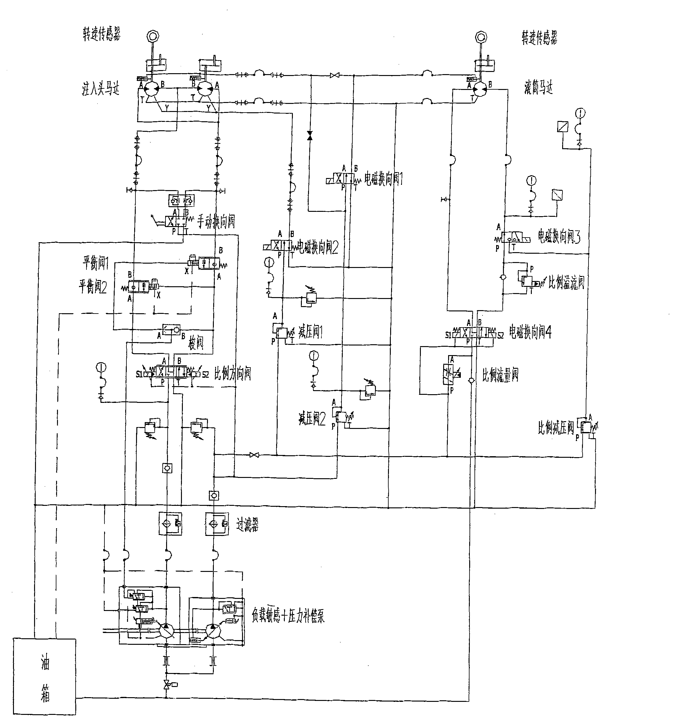
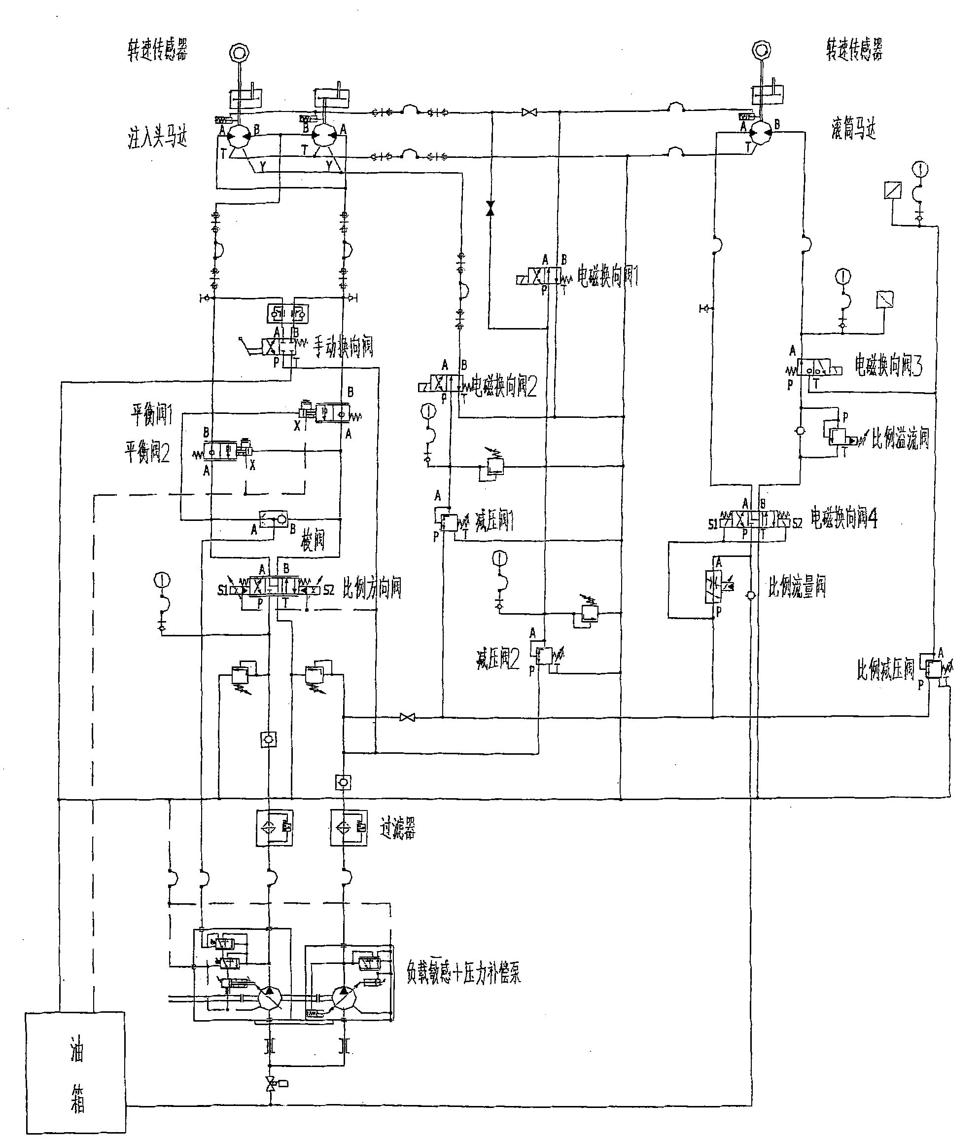
[0028] Embodiment 1: see attached figure 1 . The speed matching control device between the coiled tubing injection head and the drum of the present invention, the main components include: the model of the load sensitive pump is FRRO74BLS27. The model used for the pressure compensation pump is LRRO25CPC20. The model of proportional directional valve is DPZA-A-173. One shuttle valve model number is BGY2-220. The model of the two balancing valves is CINDY-12-B. A manual directional valve model is AH4Z61a / f. The model number of the two injection head motors is R20U+BD2-500 / 250 9HU+D40J. A drum motor model is GM1+F10+R13. The two pressure reducing valves are model MVSPM22-63. The two speed sensors are model GWM-40. The four solenoid directional valves are model DPHA-2713. A proportional relief valve model number is BVCPM22-200. A proportional pressure reducing valve model number is MVCPM22-200. A proportional flow valve model is QVHZA-A-06.

[0029] refer to figure 1 ....


PUM


Abstract

The invention provides a control device for matching the speed between an injection head of a continuous pipe assembly and a roller. The invention is applied to the continuous pipe construction in the petroleum industry and is characterized in that the device consists of a load sensing pressure compensation pump, a proportional direction valve, a shuttle valve, two equilibrium valves, a manual reversing valve, two injection head motors, a roller motor, two reducing valves, two rotating speed sensors, four electromagnetic reversing valves, a proportional overflow valve and an oil box, each component is connected and assembled according to the invention. The control device has the advantages that the cooperation control of the two subsystems of the injection head and the roller is realized,the roller injection or lifting speed is the same as the speed for loosening or winding the injection head continuous pipe, the 'back drawing force' of the continuous pipe on the roller is constant basically, thereby reducing the harm on the continuous pipe and the continuous pipe assembly, prolonging the service life, shortening the operation time, saving the operation cost and avoiding unnecessary loss caused by misoperations.

Description

technical field [0001] The invention relates to the technical field of coiled tubing in the petroleum industry, in particular to a speed matching control device between two subsystems of an injection head and a drum in coiled tubing equipment. Background technique [0002] Coiled tubing equipment and technologies in the oil industry are completely dependent on imports, and it is of great significance to develop coiled tubing equipment with independent intellectual property rights. [0003] In the imported coiled tubing equipment, the injection head and the drum are driven to rotate by the injection head motor and the drum motor respectively. The injection and lifting speeds of the injection head are controlled separately by manual control, and the unwinding and winding rotation speeds of the drum are respectively controlled by manual control. Since the operation of the injection head and the drum is manually controlled, human factors lead to inaccurate control; in addition,...

Claims


Application Information

Patent Timeline
Patent Type & Authority Patents(China)
IPC IPC(8): E21B19/084
Inventor 马青芳彭嵩王爱国邵强张燕萍
Owner BC P INC CHINA NAT PETROLEUM CORP
Why Eureka
Try Eureka