Surface flaw detection device

A defect detection and defect technology, which is applied in the direction of measuring devices, optical test defects/defects, image data processing, etc., can solve the problems of affecting detection efficiency, low degree of automation, inconvenient use, etc., and achieve the effect of improving detection efficiency

Inactive Publication Date: 2008-09-10
INST OF IND TECH GUANGZHOU & CHINESE ACADEMY OF SCI +1
View PDF0 Cites 43 Cited by
  • Summary
  • Abstract
  • Description
  • Claims
  • Application Information

AI Technical Summary

Problems solved by technology

[0006] The defect of the existing industrial inspection device is that the stage cannot be turned over, so that the optical objective lens can only observe one surface of the object to be inspected, and cannot conveniently observe other surfaces of the object to be inspected in one clamping process
For example, in the production process of watches, it is necessary to detect whether there are defects on the front and peripher

Method used


Image

  • Surface flaw detection device
  • Surface flaw detection device
  • Surface flaw detection device

Examples


Embodiment 1

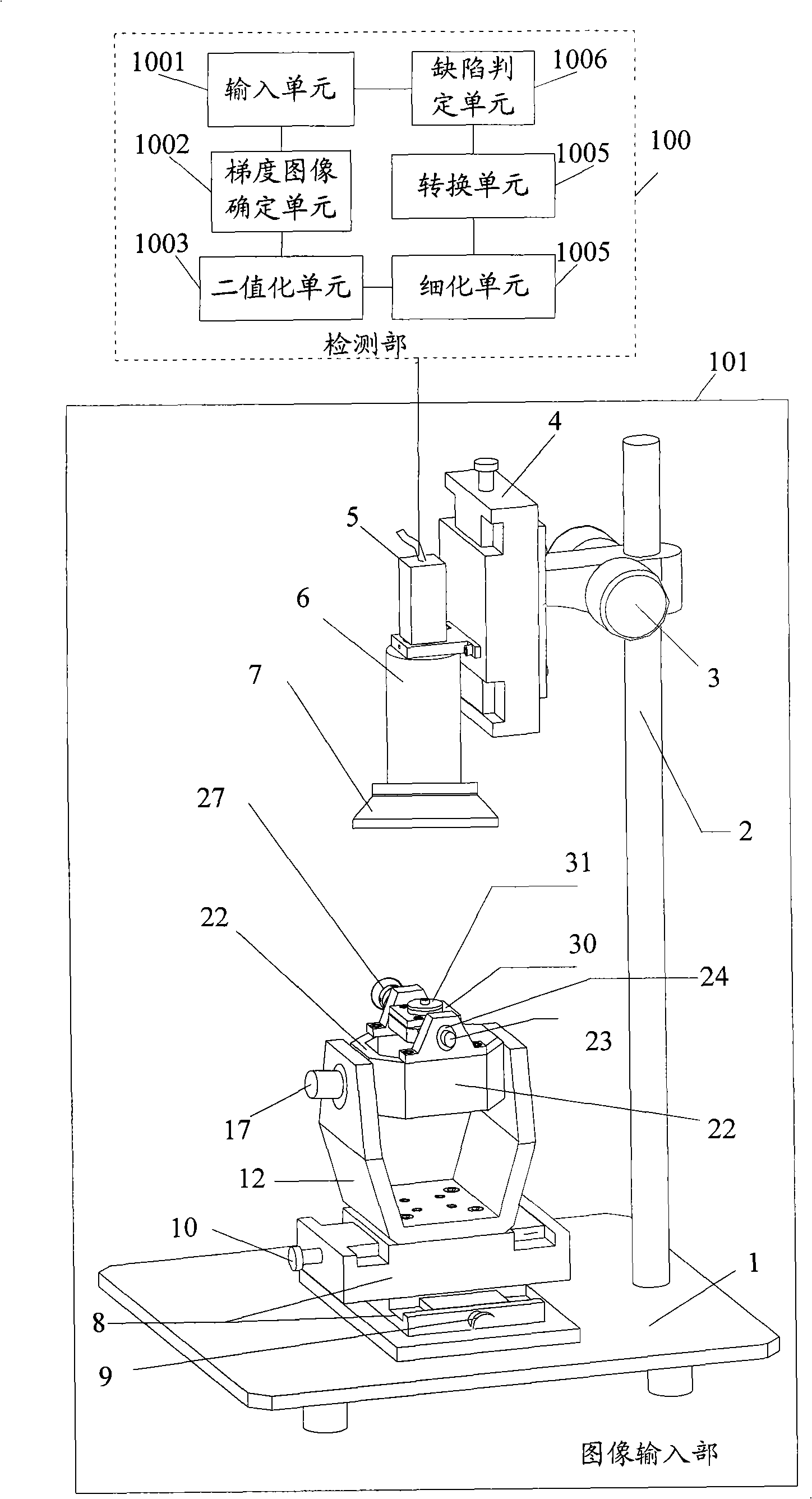
[0034] figure 1 It is a schematic structural diagram of the surface defect detection device provided in this embodiment. As shown in the figure, the device is composed of an image input unit 11 and a detection unit 10 .

[0035] Wherein the image input unit 101 includes:

[0036] Support table 1, support member 2, focusing mechanism 3 and 4, optical objective lens 6, imaging device 5 connected to the top of optical objective lens 6, detection mechanism 801 connected with said imaging device 5, latitude and longitude adjustment table 8, installed in the latitude and longitude The rolling mechanism (rolling support 12, rolling shaft 13 and rolling motor 17) and pitching mechanism (comprising pitching support 22, pitching shaft 23 and pitching motor 27) on the adjustment table 8, and the pitching shaft 23 on the stage 30 . in:

[0037] The support member 2 is fixed on the support platform 1 for supporting the optical objective lens 6;

[0038] The optical objective lens 6 is ...

Embodiment 2

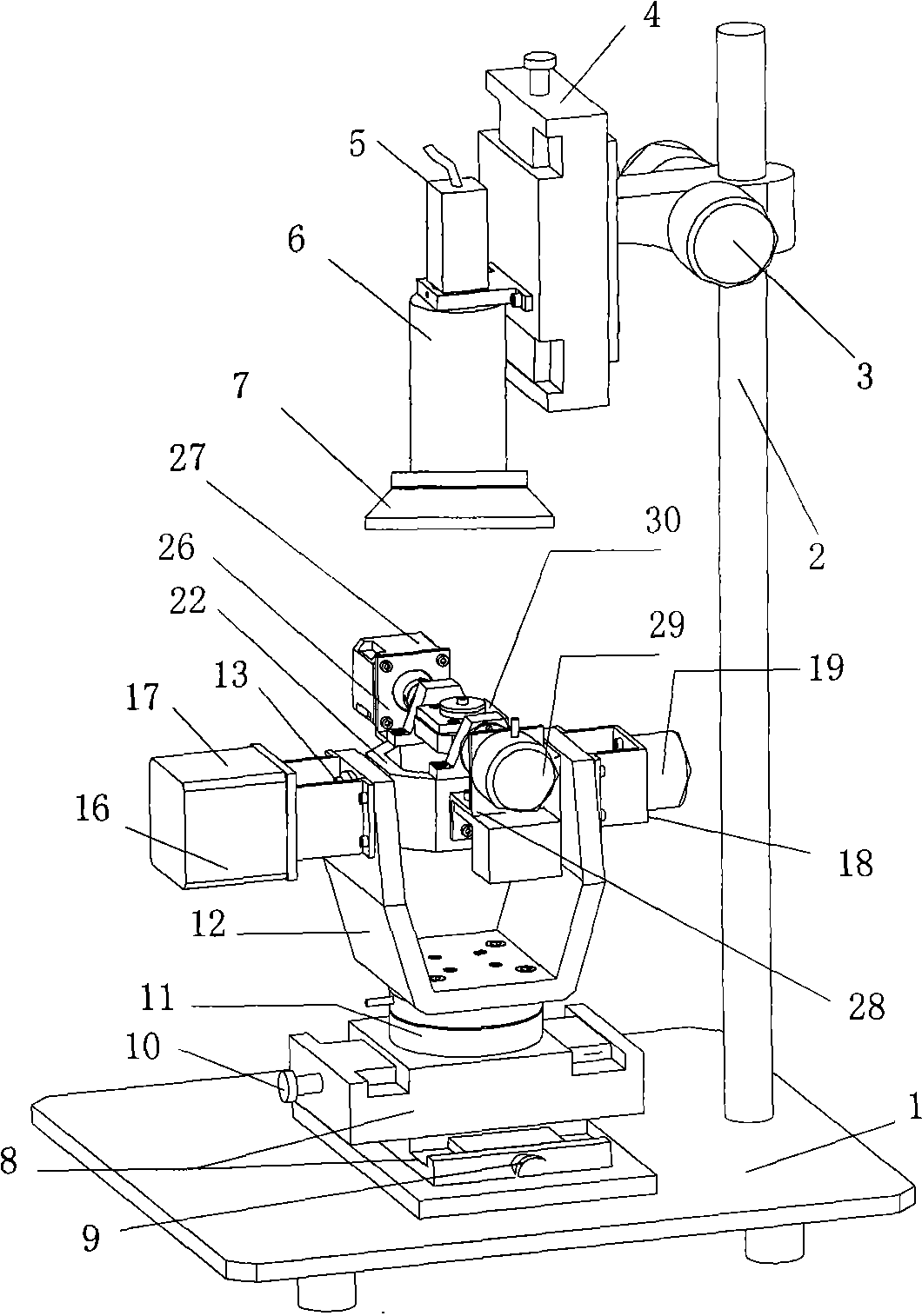
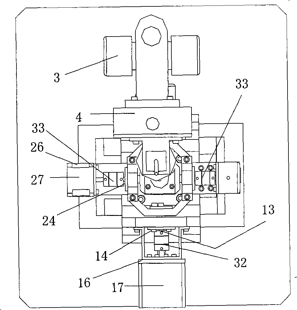
[0080] figure 2 It is another schematic perspective view of the structure of the image input unit in the surface defect detection device provided in this embodiment, image 3 is corresponding figure 2 A schematic diagram of the top view state of the image input unit, Figure 4 and Figure 5 yes figure 2 The corresponding side view of the image input section.

[0081] The structure and embodiment of the surface defect detection device of this embodiment figure 1 The structures shown are roughly the same, the difference is that the image input part of this embodiment is different from that of Embodiment 1, the main difference is that the image input part in this embodiment also includes an encoder feedback system, which is the same as Together, the motor drive system forms the closed-loop control circuit. The encoder feedback system includes a pan encoder 19, a pitch encoder 29 and a control circuit (not shown in the figure).

[0082] More specifically, in this embodim...

Embodiment 3

[0091] Figure 6 It is a schematic structural diagram of the surface defect detection device of this embodiment. As shown in the figure, the difference between this embodiment and Embodiment 1 is that the detection unit 60 of the device may also include:

[0092] The defect level determination unit 601 is configured to determine the defect level of the defect according to the area and / or shape of the defect determined by the defect determination unit 1006, so as to facilitate subsequent corresponding processing according to the defect level.

[0093] In the process of industrial inspection, after the defect is detected, the defect can also be divided, and the defect can be dealt with accordingly according to the division. (the shape of the defect edge of the closed loop), and / or, determine whether the defect is a point defect, a line defect, or a surface defect, so as to perform corresponding processing according to the defect level.


PUM


Abstract

The invention relates to the detection field, disclosing a detection device of surface defects. The detection device of surface defects, which includes an image input part and a detection part, consists of a rolling mechanism and a pitching mechanism to drive an object stage to rotate towards four directions. A loading process can test a plurality of surfaces of a detected object; therefore, the device is convenient in use. Moreover, the coordination of a rolling motor, a pitching motor and a control circuit leads the device to conveniently control the rotation direction, swing angle and speed of the object stage and to collect images of the detected object in various angles, thus being beneficial to the detection part to detect comprehensively the defect according to the original image taken from various input angles and beneficial to improving the defect detection accuracy. In addition, the device can automatically adjust and finish the image capture of the detected objects from various angles as well as image detection, obviously, the device is favorable to improving automatic detection and detection efficiency.

Description

technical field [0001] The invention relates to the field of automatic detection, in particular to a surface defect detection device. Background technique [0002] In the process of industrial production, it is often necessary to inspect and measure some samples and components. For example, when producing high-end watches, it is necessary to detect some small appearance defects (scratches, pits, chipping, cracks, sand holes, etc.) of the watch case. In the prior art, human eyes are generally used to directly detect and identify surface defects of samples and components, but this method has the following defects on the one hand: [0003] First of all, the work efficiency of applying this method is very low, which is not conducive to saving labor and is not conducive to improving production efficiency. [0004] Secondly, due to human factors, especially when a large number of products need to be inspected, inspectors are prone to eye fatigue, resulting in misjudgments and mi...

Claims


Application Information

Patent Timeline
IPC IPC(8): G01N21/88G01N21/13G06T7/60
Inventor 邬纪泽李伟邓钊沈大刚蒲常华肖浩何宇
Owner INST OF IND TECH GUANGZHOU & CHINESE ACADEMY OF SCI
Why Eureka
Try Eureka