
Synthetic aperture radiometers image-forming correction method

A comprehensive aperture and correction method technology, applied in the direction of re-radiation, radio wave reflection/re-radiation, instruments, etc., can solve the problems of complex measurement and calculation, achieve simple measurement, small amount of calculation, and improve the effect of imaging

Inactive Publication Date: 2008-09-10
HUAZHONG UNIV OF SCI & TECH
View PDF0 Cites 18 Cited by
  • Summary
  • Abstract
  • Description
  • Claims
  • Application Information

AI Technical Summary

Problems solved by technology

[0004] The object of the present invention is to provide a synthetic aperture radiometer imaging correction method, which overcomes the shortcomings of the G matrix correction method measurement and calculation complexity

Method used


Image

  • Synthetic aperture radiometers image-forming correction method
  • Synthetic aperture radiometers image-forming correction method
  • Synthetic aperture radiometers image-forming correction method

Examples


Embodiment

[0051] 1) Experimental equipment:

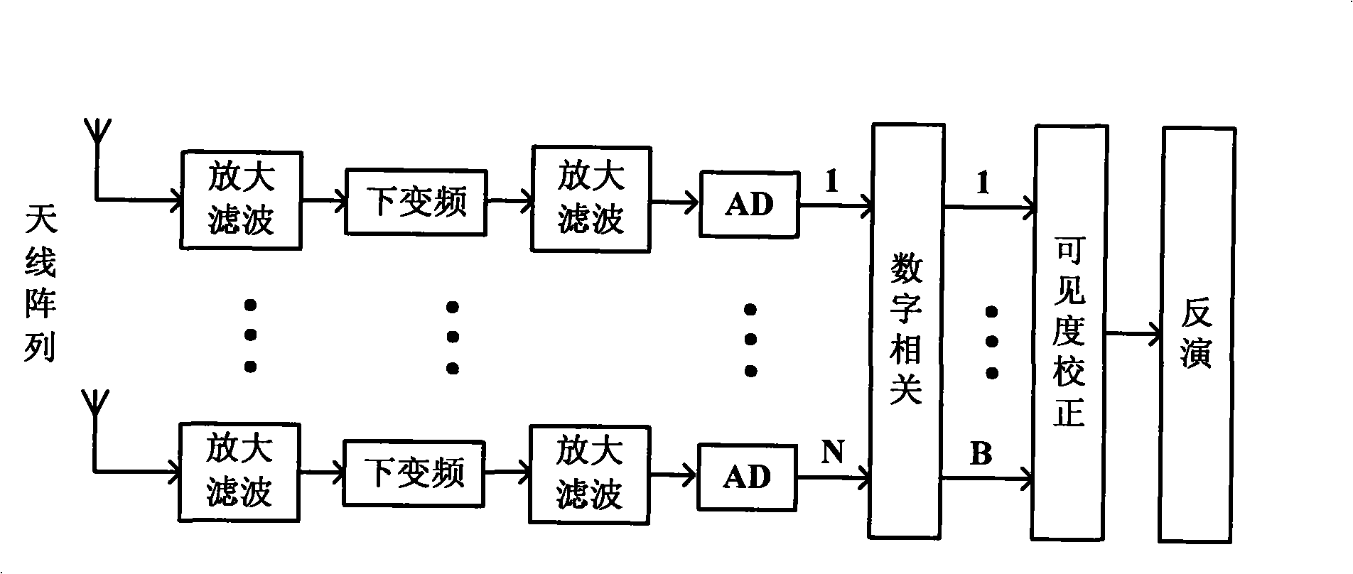
[0052] ①Microwave thermal radiation array receiving system, the specific parameters are as follows:

[0053] Working band: 8mm band

[0054] Number of antenna elements: 16

[0055] The array adopts a minimum redundant array arrangement of 1 times the wavelength: the maximum baseline length is 90 times the wavelength, and the length is 741.2mm

[0056] System resolution: 0.011rad

[0057] ② Two sources of solid noise:

[0058] One of the solid noise sources is used instead of the artificial target in the experiment because they have the same signal characteristics. Another noise source acts as an external correction source. Solid noise source parameters: the operating frequency is 34.5-37.5GHz, and the ultra-noise ratio is 23dB.

[0059] 2) Experimental design:

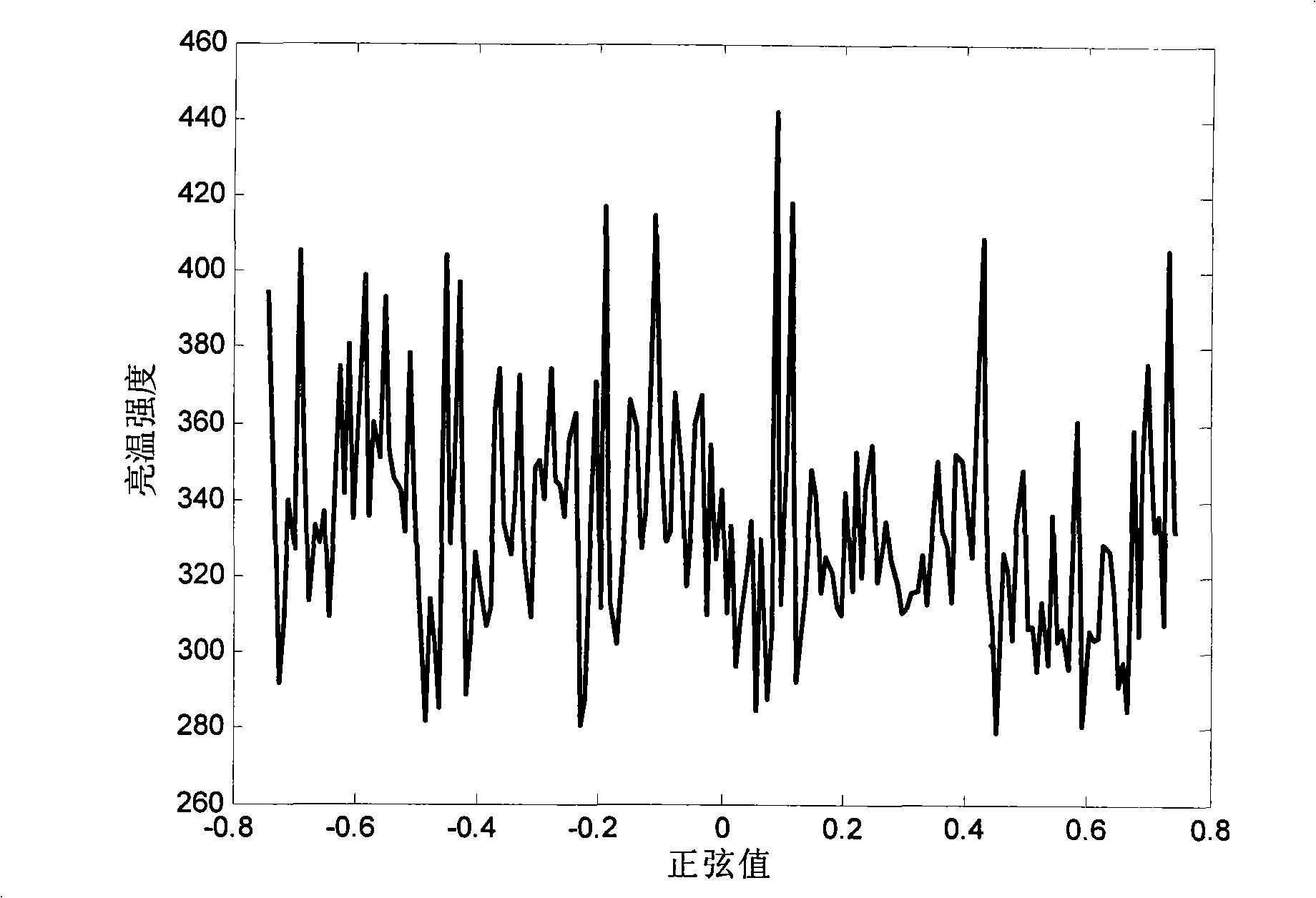
[0060] Place a solid noise source as an artificial target at a distance of 675cm from the array radiometer system at an angle of -2°; turn on the noise source to measure the out...


PUM


Abstract

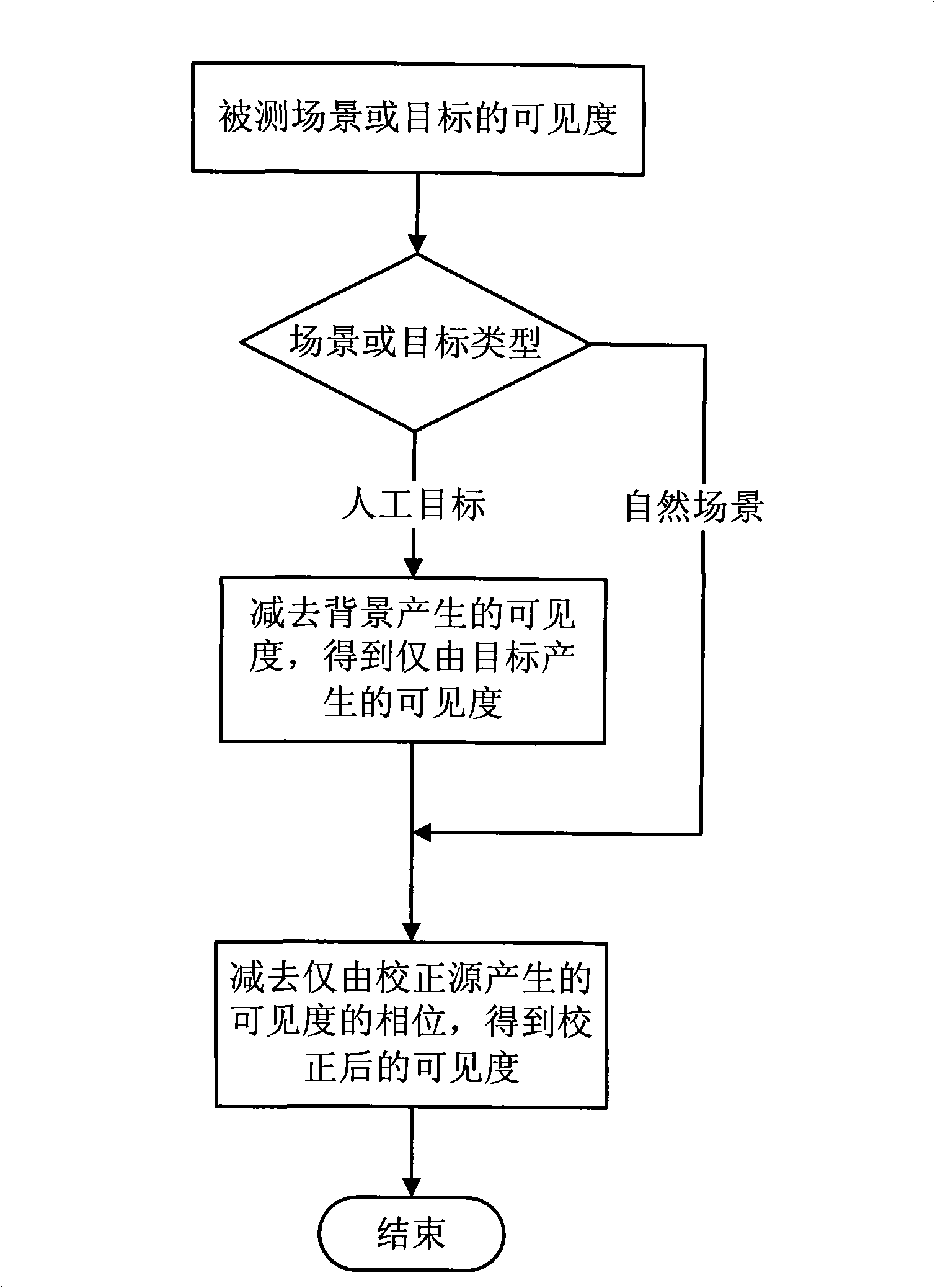
The invention belongs to the technical field of microwave remote sensing and detection, relating to an imaging correction method for a synthetic aperture radiometer, wherein, the method first measures the visibility output of every baseline of a background and a channel background and then an external source (a signal source or a noise source) is placed within the field of view to measure the visibility output of every baseline; the twice measured visibility outputs are subtracted by the baseline to obtain the visibility output caused by the external source; the visibility output of the measured field is measured to obtain a corrected invisibility by subtracting a related output phase caused by the external source from the obtained output phase, and then obtain an image by inversion so as to obtain a corrected image of the measured field. The correction method can improve the imaging performance of the interference synthetic aperture radiometer and has the advantages of simple measurement, no need for support from a turntable control system, less calculating amounts and period measurement. The correction method is not confined into distance field measurement and can also be used under near field condition found by emulation and experiment.

Description

technical field [0001] The invention relates to the technical field of microwave remote sensing and detection, in particular to an imaging correction method for a synthetic aperture radiometer. Background technique [0002] Correction technology, especially phase correction technology, plays an important role in improving the imaging effect of synthetic aperture radiometer. [0003] A typical correction method is the G matrix correction-inversion method, which generates a matrix including system errors by measuring the response of the imaging system to each point in space, and then uses the matrix to perform inversion to reduce the impact of errors on system imaging performance. Most of the interferometric synthetic aperture systems that have existed or are being studied in the world, such as ESTAR, MIRAS, and GeoSTAR, mostly use this method, but this method has the following disadvantages: First, the measurement of the G matrix is ​​time-consuming and labor-intensive. The...

Claims


Application Information

Patent Timeline
IPC IPC(8): G01S7/40G01S13/90
Inventor 李青侠陈柯陈良兵郭伟胡飞朱耀庭何方敏董健
Owner HUAZHONG UNIV OF SCI & TECH
Learn More