Fuel engine servo loading device and its dynamic optimization operation control method

A fuel engine and loading device technology, which is applied in engine control, motor generator control, electronic reversing motor control, etc., can solve the problems of low transmission efficiency, energy saving effect discount, large inertia, etc., and achieve the effect of reducing exhaust emissions and saving energy obvious effect

Active Publication Date: 2008-09-10
桂林星辰科技股份有限公司
View PDF3 Cites 19 Cited by
  • Summary
  • Abstract
  • Description
  • Claims
  • Application Information

AI Technical Summary

Problems solved by technology

However, the CVT also has obvious limitations: firstly, the mechanical structure is relatively complex, so its manufacturing cost is high; furthermore, the inertia of the mechanical structure and hydraulic system is large, so the adjustment speed is slow, especially when the engine throttle or external load torque changes dynamically. When the road conditions change frequently, the accelerator changes frequently, and the speed changes frequently, the continuously variable transmission (CVT) cannot adjust the ratio quickly and accurately, and the probability of the fuel engine working on the optimal efficiency operating curve is still very low; in addition, the CVT (CVT) transmission efficiency is lower than general gear transmission
[0008] However, because the characteristics of the same type of fuel engine are also dispersed, it is impossible to unify them. In addition, with the continuous aging of fuel engine parts, changes in fuel used, changes in air mixing ratio, changes in engine temperature and other external factors, the actual performance of a fuel engine The best efficiency operating curve often deviates from the best efficiency operating curve provided by the original manufacturer or tested
That is to say, the fuel engine is controlled according to the optimal efficiency operating curve originally stored by the servo loading device, and the torque calculated by using the stored optimal efficiency operating curve according to the current speed is not the best efficiency matching the speed. Torque, that is to say, the servo loading device does not make the fuel engine work on the changed real best efficiency operating curve, so the energy saving effect will be compromised

Method used


Image

  • Fuel engine servo loading device and its dynamic optimization operation control method
  • Fuel engine servo loading device and its dynamic optimization operation control method
  • Fuel engine servo loading device and its dynamic optimization operation control method

Examples


Embodiment Construction

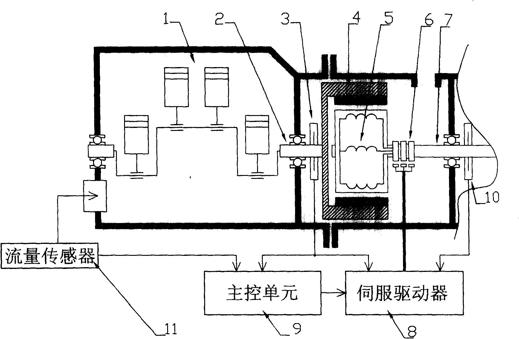
[0026] The structure of the embodiment of the servo loading device of the fuel engine is as follows figure 1 As shown, the fuel engine 1 is connected to a servo control device including a permanent magnet synchronous motor and a servo driver. The outer rotor 4 of the motor is directly connected to the output shaft 2 of the fuel engine 1; the outer rotor 4 of the motor is embedded with permanent magnet material, which is The inner rotor 5 and the inner rotor 5 are windings wound on the iron core, and the shaft of the inner rotor 5 is the output shaft 7 of the device. A speed / position sensor 3 is installed on the outer rotor 4. The speed / position sensor 3 is connected with the main control unit 9 and the servo driver 8. A position sensor 10 is installed on the shaft of the inner rotor 5, and the position sensor 10 is connected with the servo driver 8. The main control unit 9 is connected to the servo driver 8. The servo driver 8 is connected to the winding of the inner rotor 5 thro...


PUM


Abstract

The invention relates to a servo-loading device of a fuel engine, an external rotor shaft of the device is connected with an output shaft of the engine; the interior of the external rotor is an internal rotor, while an internal rotor shaft is the output shaft of the device; either the internal rotor or the external rotor is wedged with one permanent magnet, and the other rotor is a winding; the winding passes a collecting ring and is connected with a servo drive. A velocity / position sensor of the external rotor is connected with a main control unit and the servo drive, position sensor of the internal rotor is connected with the servo drive, while a flux sensor in an oil path is connected with the main control unit. The main control unit memorizes the best efficiency curve and the oil consumption of per mechanical energy unit of different points in the curve. The dynamic control method for the optimized running of the device is that: the main control unit determines the best torque value T according to the best efficiency curve at a current rotating speed, and automatically controls the pilot running of the engine on the basis of a torque of T plus dT, and calculates the oil consumption value of per mechanical energy unit at this time and compares with the value of the best efficiency curve; if the oil consumption for the pilot running is a lower one, T plus dT substitutes T and is memorized, and the optimization is continued, on the contrary, a reverse optimization is carried; the process is circulated repeatedly to memorize newer practical best efficiency curve.

Description

(1) Technical field [0001] The invention relates to the technical field of energy saving, in particular to a fuel engine servo loading device and a dynamic optimization operation control method. Due to changes in engine component conditions or fuel quality and other factors, the speed and torque matching data for the best efficiency of the fuel engine will change. The fuel engine servo loading device and its operation control method can automatically dynamically optimize and correct in real time. The best efficiency operation curve of the engine keeps the engine working on the actual best efficiency operation curve and achieves the purpose of further saving energy. (2) Background technology [0002] Tests have shown that there are several working points with different speeds and torques in the output of a certain mechanical power of a fuel engine, and there is a minimum fuel consumption point among multiple working points with the same mechanical power of the engine output, which...

Claims


Application Information

Patent Timeline
Patent Type & Authority Applications(China)
IPC IPC(8): H02K29/06F02D28/00F02D45/00H02P6/08H02P6/16H02P21/00G01M15/00F02D29/06F02D41/14F02D41/24
CPCY02T10/84
Inventor 吕虹
Owner 桂林星辰科技股份有限公司
Why Eureka
Try Eureka