
Method and device for removing metallic material of high-speed conveyer belt bulk cargo

A conveyor belt and material metal technology, applied in the direction of conveyor control devices, conveyor objects, transportation and packaging, etc., can solve the problems of high-speed conveyor belt safety threats, time lag, and easy to be "thrown out", so as to improve equipment safety and The effect of delivery efficiency

Active Publication Date: 2008-09-17
BAOSHAN IRON & STEEL CO LTD +1
View PDF2 Cites 10 Cited by
  • Summary
  • Abstract
  • Description
  • Claims
  • Application Information

AI Technical Summary

Problems solved by technology

However, due to the inertia of the metal objects on the conveyor belt synchronous with the conveyor belt speed, especially for high-speed conveyor belts, the iron-type magnetic-conducting material in the ore has just "broke out" from the ore, and it will be absorbed by its own Inertial throwing, and the greater the weight of the magnetic material, the easier it is to be "thrown". For this reason, sometimes "slipped" scrap steel remains on the conveyor belt, posing a threat to the safety of the high-speed conveyor belt
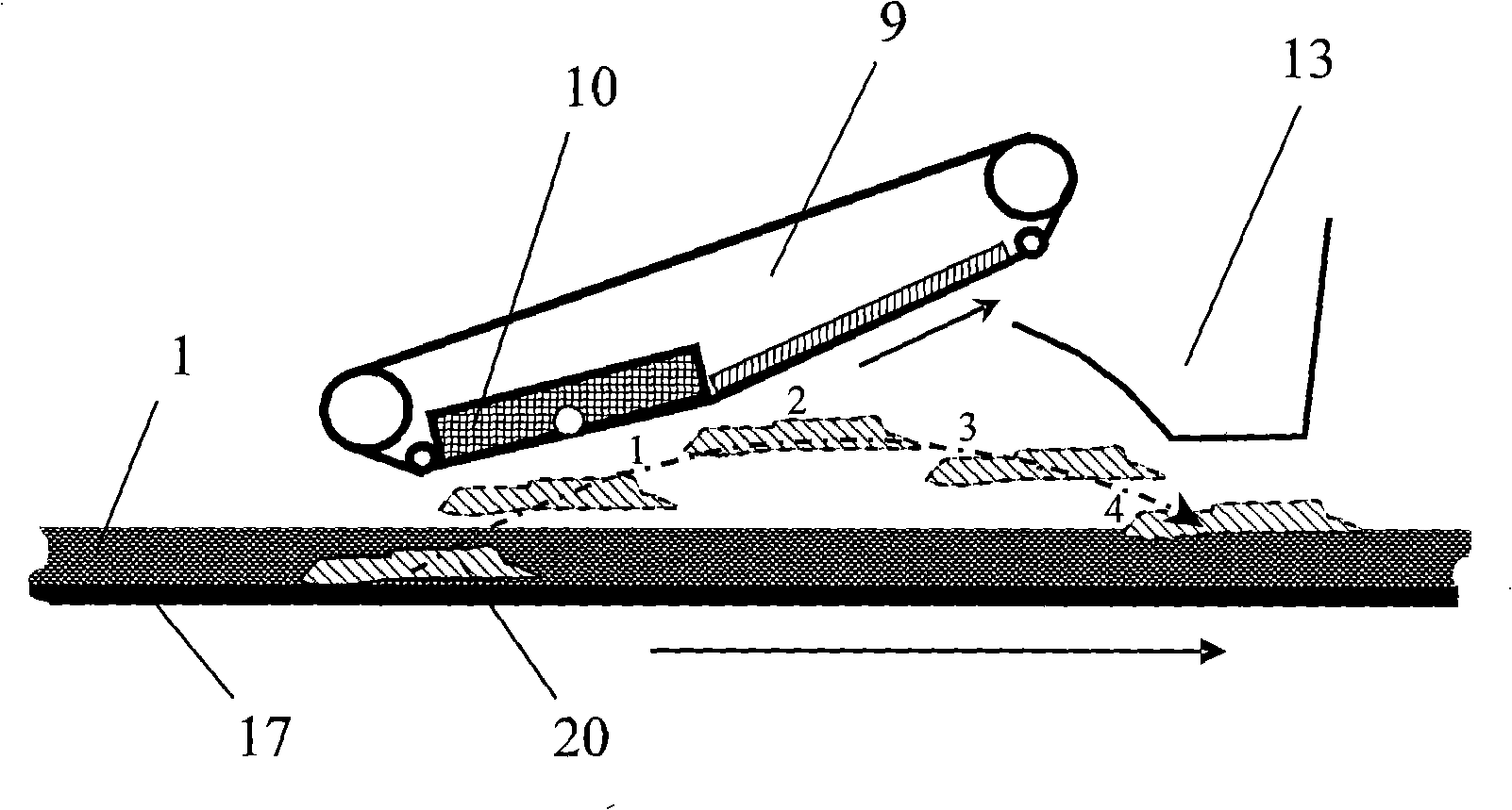
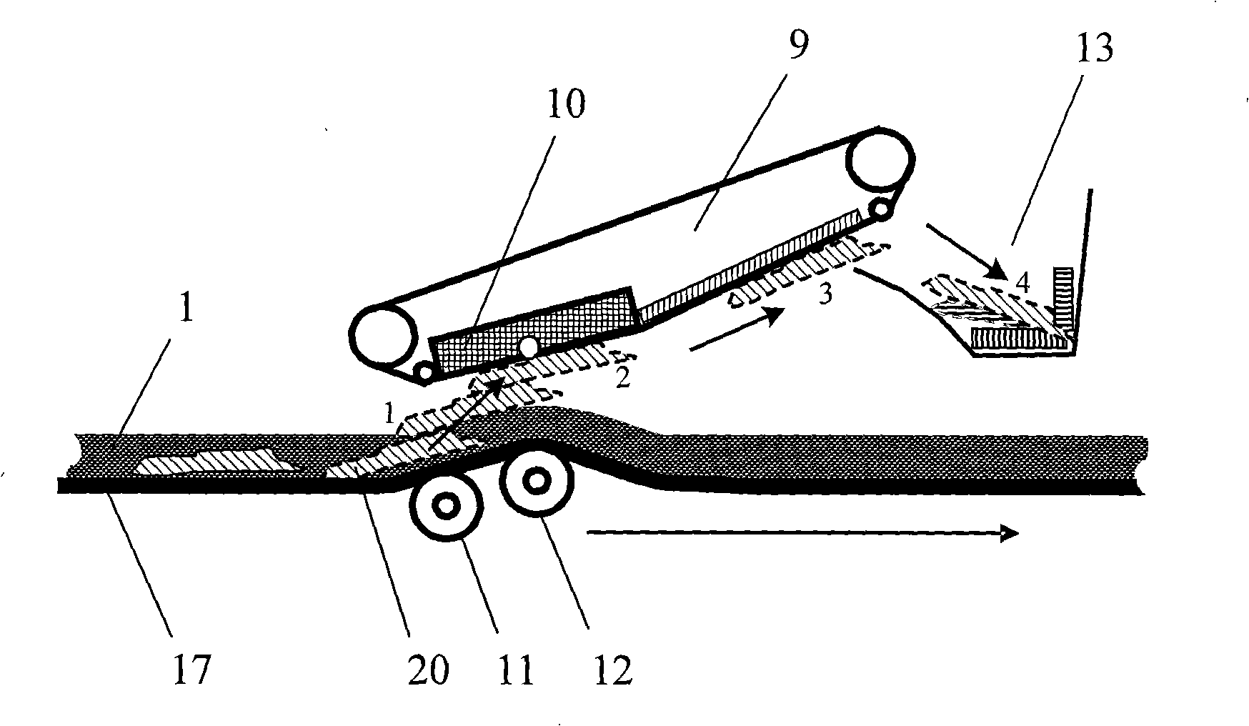
Chinese patent 02265152.7 discloses a "parallel recovery type iron removal device", and Chinese patent 200610008704.9 discloses a "combined magnetic ore iron remover". figure 1 When the scrap iron block 20 passes through the bottom of the iron remover 9 electromagnet 10 (the area with the largest magnetic intensity), due to the effect of the electromagnet 10, the scrap iron block 20 mixed in the mineral material 1 will be sucked, and the scrap iron block 20 will be sucked hereby. 20 must break through the resistance and gravity of mineral material 1, and then break through the ground, resulting in a time difference
[0007] In addition, for high-speed conveyor belts conveying bulk materials, there are also non-magnetic metals (such as stainless steel) in the bulk materials, which has become a new threat to the bulk material conveyor belt; while the existing technology only It can remove iron, but there is a lack of countermeasures for all-round removal of metals in bulk materials

Method used


Image

  • Method and device for removing metallic material of high-speed conveyer belt bulk cargo
  • Method and device for removing metallic material of high-speed conveyer belt bulk cargo
  • Method and device for removing metallic material of high-speed conveyer belt bulk cargo

Examples


Embodiment Construction

[0028] The present invention will be further described below in conjunction with the accompanying drawings and specific embodiments.

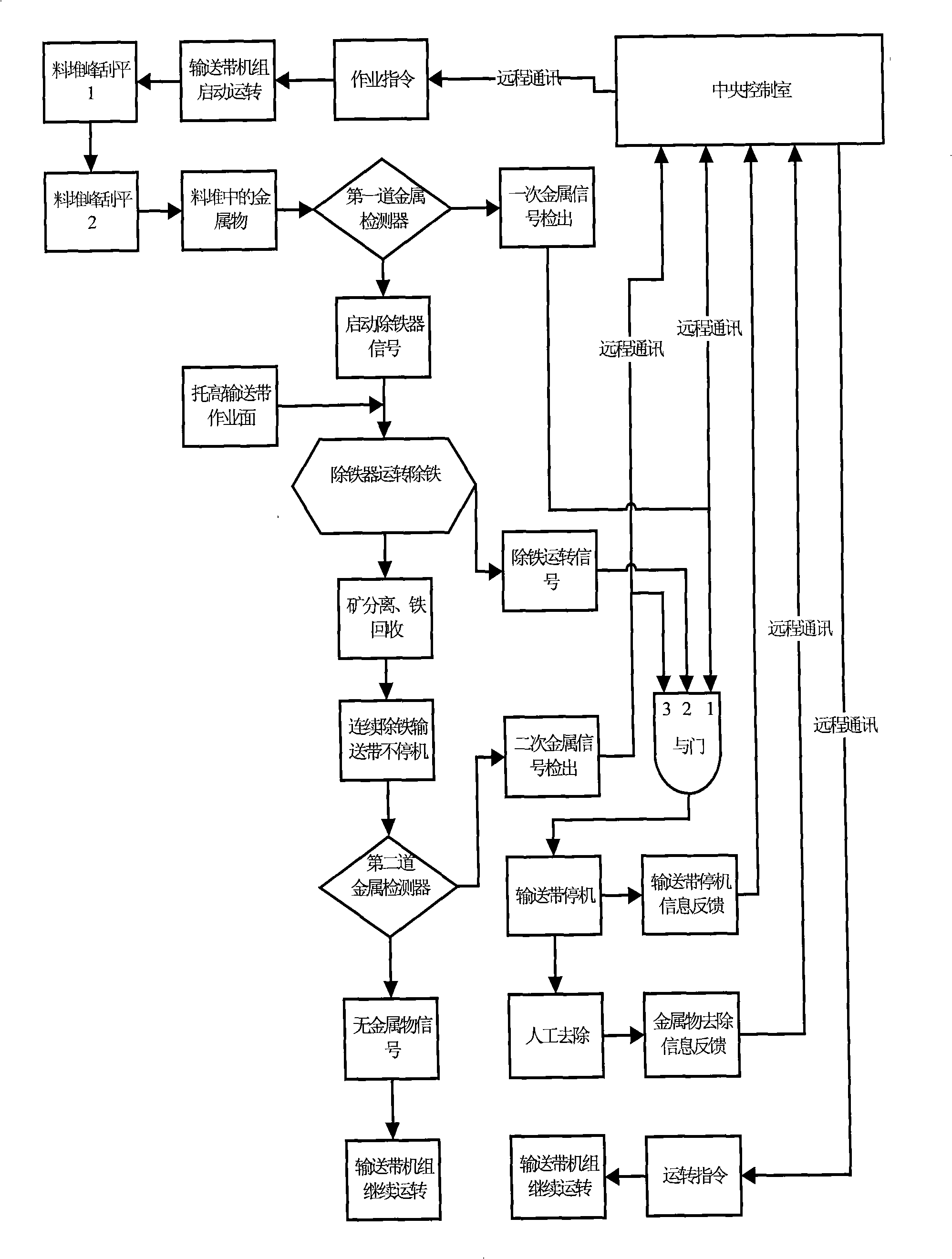
[0029] see image 3 , Figure 4 , a method for removing metal objects from bulk materials on high-speed conveyor belts. The "tip" is scraped off by two to three stockpile scrapers placed on the high-speed conveyor belt, and the metal objects in the conveyor belt stockpile pass through the first metal detector and give two signals at the same time: a metal removal signal Drive the iron remover, another signal is sent to the input terminal "1" of the AND gate circuit through a metal signal detection, and at the same time, the metal signal detection transmits the metal object information to the central control room through remote communication. After the iron remover is activated, the iron remover runs to remove iron. An adjustable conveyor belt support device is installed under the conveyor belt below the main electromagnet adsorption surface ...


PUM


Abstract

The invention discloses a method and a device for removing metal in high-speed conveyer belt bulk materials. Compared with the prior art, the method is characterized in adding a second metal detector, an AND gate logic control circuit, a material pile strickle and a conveyer belt bracket; a plurality of single components form a control subsystem connected with a console cabinet. The method is suitable for conveying the bulk materials by means of conveyer belts in steel, wharf, logistics, mining and storage industry. The method has the advantages of integrating communication, control and data exchange, enabling linkage with the console cabinet, removing the non-magnetic metal of high-speed conveyer belt, and improving equipment safety and conveyance efficiency of the high-speed conveyer belt.

Description

(1) Technical field [0001] The invention relates to a method and a device for removing metal objects in bulk materials on high-speed conveyor belts. (2) Background technology [0002] The belt conveyor for long-distance transportation of granular and powdery bulk materials (such as iron ore, etc.) is a kind of efficient transportation equipment today, and is widely used in metallurgical enterprises, docks, ore yard storage and other industries. During the transportation of bulk materials, metal wastes are often mixed in, especially the long and sharp metal objects that are mixed in are the most harmful. Belt, so that the entire conveyor belt cut off production, resulting in huge losses. The metals mixed in bulk materials such as coal and ore are basically iron and steel substances. These substances are generally mixed in during the mining, transportation and processing of ore production, such as: machinery, equipment, and tools. Parts, structural parts, waste, etc. In ord...

Claims


Application Information

Patent Timeline
Patent Type & Authority Applications(China)
IPC IPC(8): B65G43/00B65G43/08B65G47/00B03C1/16
Inventor 孔利明韩明明肖苏孙品生周一农李斌徐敏坚李荣江通吴剑民
Owner BAOSHAN IRON & STEEL CO LTD
Learn More