
Floating shaft cog-wheel coupling correcting device

A technology of calibrating device and coupling, applied in the direction of angle/taper measurement, etc., can solve the problems of not very strict installation accuracy requirements, unusable couplings, increase the number of calibrations, etc., so as to shorten the maintenance time, reduce the maintenance cost, The effect of prolonging the operating cycle

Inactive Publication Date: 2008-09-17
CHONGQING IRON & STEEL (GRP) CO LTD
View PDF0 Cites 0 Cited by
  • Summary
  • Abstract
  • Description
  • Claims
  • Application Information

AI Technical Summary

Problems solved by technology

Calibration based on experience, due to human subjective error, leads to large eccentricity, increases the number of calibrations, prolongs the calibration time, and reduces work efficiency; although the method of making a micron meter has high precision, the equipment cost is high and the calibration time is long. Generally, this method is only used when the equipment is overhauled. At the same time, it takes up a lot of space during calibration, and it cannot be used for the coupling of small equipment.
Especially for floating shaft gear couplings of small equipment, the requirements for installation accuracy are not very strict, so it is not suitable for micrometer calibration

Method used


Image

  • Floating shaft cog-wheel coupling correcting device
  • Floating shaft cog-wheel coupling correcting device
  • Floating shaft cog-wheel coupling correcting device

Examples


Embodiment 1

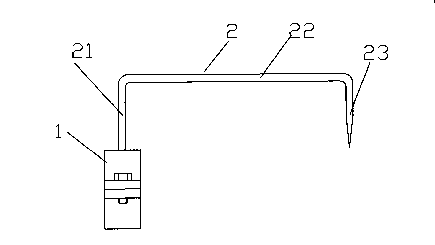
[0020] Embodiment 1, the calibration reference plane in this embodiment is the outer circular surface of the floating shaft 5 .

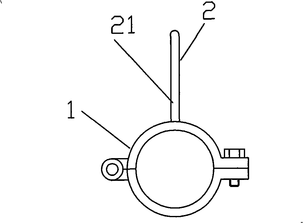
[0021] figure 1 It is a structural schematic diagram of Embodiment 1 of the present invention, figure 2 for figure 1 side view, Figure 5 It is a schematic diagram of the use state of the present invention, as shown in the figure: the floating shaft gear coupling correction device of this embodiment includes a ring body snap ring 1 and a correction rod 2 composed of two half rings, and the ring body snap ring 1. When in use, the gap fit is sleeved on the outer circle of the coupling 4 connected to the floating shaft 5. In this embodiment, the inner diameter of the ring snap ring 1 is equal to the outer diameter of the coupling 4 connected to the floating shaft 5, forming a ring One side of the two halves of the body snap ring 1 is connected by a hinge, and the other side is connected by bolts. During installation, the connecting bolts are adjust...

Embodiment 2

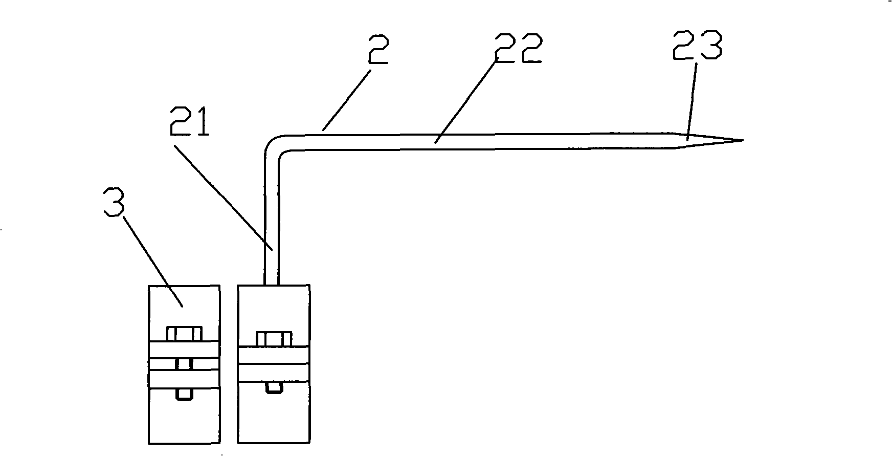
[0023] Embodiment 2, the calibration reference plane in this embodiment is the end face of the motor brake connected to the floating shaft.

[0024] image 3 It is a schematic structural diagram of Embodiment 2 of the present invention, Figure 4 It is a schematic diagram of the structure of the fixed ring of the torus, Figure 5 It is a schematic diagram of the use state of the present invention, as shown in the figure: the floating shaft gear coupling correction device of this embodiment includes a ring body snap ring 1 and a correction rod 2 composed of two half rings, and the ring body snap ring 1. When in use, it fits loosely on the outer circle of the floating shaft 5. In this embodiment, the inner diameter of the torus clasp 1 is equal to the diameter of the outer circle of the floating shaft 5, and one side of the two halves of the torus clasp 1 is connected by a hinge. , the other side is connected by bolts. During installation, ensure that the ring body snap ring 1...


PUM


Abstract

Disclosed is a correcting device of floating shaft tooth shape shaft coupling, including circular snap ring consisting of two hemi-toroidals and proof rod that includes fixed end which is fixed on the circular snap ring, bar body pointing to correction datum plane when use and correcting end. The invention can accurately correct concentricity between the floating shaft and power equipment or driving equipment, extending operating cycle of the equipment, decreasing damage rate of rotatable part, reducing repair cost, saving correction time and increasing production efficiency.

Description

technical field [0001] The invention relates to a correction device for adjusting the coaxiality of a shaft coupling, in particular to a correction device for a toothed shaft coupling with a floating shaft. Background technique [0002] Floating shaft toothed couplings can transmit large torques and allow large offsets, and do not require high installation accuracy. The floating shaft coupling includes external teeth arranged at both ends of the floating shaft, and the two ends of the floating shaft are meshed to transmit torque through the internal and external teeth. However, the degree of eccentricity between the floating shaft and the power shaft and transmission shaft should not be too large. If the coaxiality deviation between the floating shaft and the rotating shaft of the connected equipment is too large, the tooth end faces of the same side of the inner and outer gear sleeves will not maintain the same plane. The tooth shape is worn during operation, and the mecha...

Claims


Application Information

Patent Timeline
IPC IPC(8): G01B5/25
Inventor 李鹏张翔
Owner CHONGQING IRON & STEEL (GRP) CO LTD
Learn More