Three-way ball valve

A three-way ball valve and valve seat technology, used in multi-way valves, valve details, valve devices, etc., can solve the problems of large valve body size, poor medium flow, small flow rate, etc., and achieve large flow channel space and flow. Smooth, volume-reducing effect

Inactive Publication Date: 2008-09-24
四川华林自控科技有限公司
View PDF0 Cites 2 Cited by
  • Summary
  • Abstract
  • Description
  • Claims
  • Application Information

AI Technical Summary

Problems solved by technology

[0003] First, because the valve core is spherical, the medium flow path must pass through the valve core. Therefore, the diameter of the valve is completely determined by the diameter of the through hole on the valve core. Limited by the volume of the ball valve core, the diameter of the through hole cannot be too large. The flow cross-sectional area is limited, and the valve with a certain nominal diameter has a large valve body, large material consumption, and high cost
[0004] Second, the medium flow path in the valve core turns sharply at 90°, the resistance is large, the medium flow is not smooth, and the flow rate becomes smaller. When the delivery flow rate and pressure difference are determined, it is necessary to choose a large-sized valve, which is uneconomical.
Especially, when it is used to convey the medium that is easy to crystallize or the medium containing solid impurities, the crystallization or solid impurities are easy to gather at the corner of the flow channel, causing blockage, affecting the action of the valve or even being stuck and unable to operate, causing accidents
Crystal or solid impurities will also enter the mating surface between the ball core and the valve seat, causing hard friction, damaging the seal, causing internal leakage of the valve, and reducing the service life of the valve
[0005] In addition, the seat of the traditional three-way ball valve is a conventional hard-sealed seat, the sealing surfaces of the valve core and seat are easy to wear, and the service life is not long

Method used


Image

  • Three-way ball valve
  • Three-way ball valve
  • Three-way ball valve

Examples


Embodiment Construction

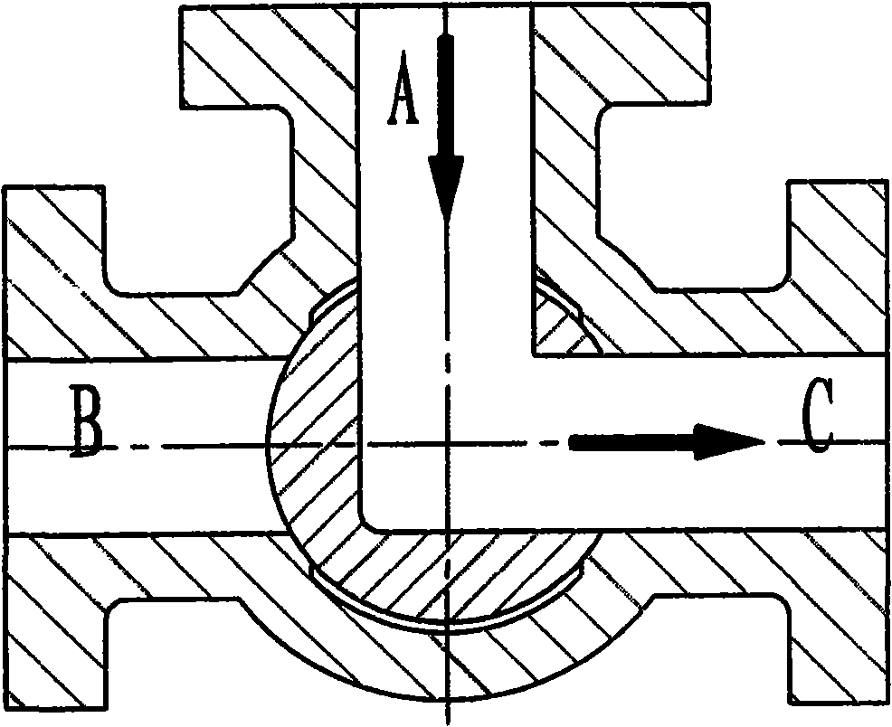
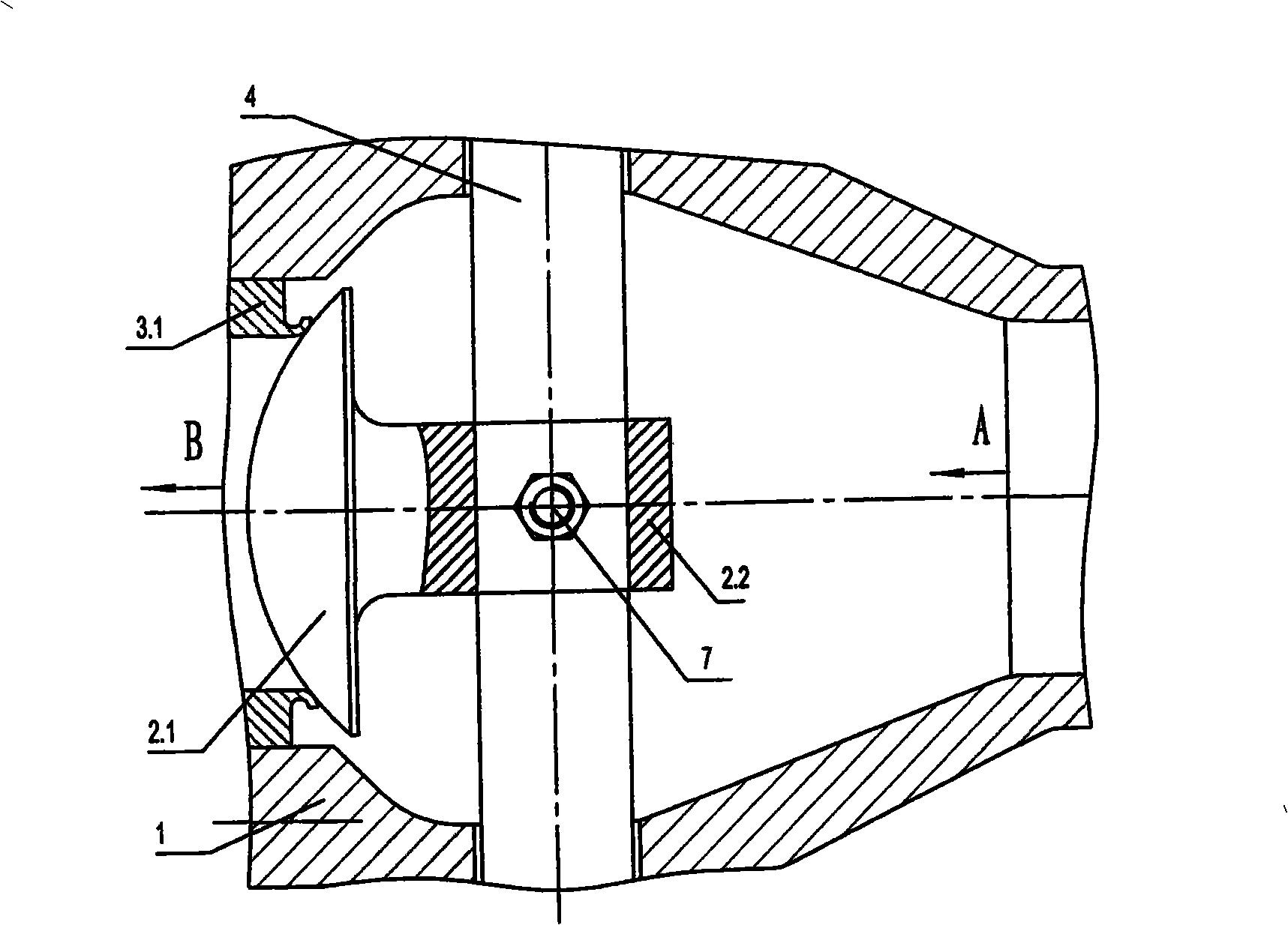
[0026] see image 3 , Figure 4 : The three-way ball valve includes a valve body 1, a valve seat 3, a valve core 2, and a valve stem 4. The valve body 1 has a medium inflow channel A and two medium outflow channels B and C, and the inner channels of the medium outflow channels B and C are The ports are respectively provided with valve seats 3 (3.1, 3.2).

[0027] The characteristic of this three-way ball valve is that the valve core 2 is designed as a special structure, which is composed of two parts, the spherical crown 2.1 and the handle 2.2. The spherical crown 2.1 is hemispherical, with a spherical surface and a flat surface; Valve seat 3; handle 2.2 is located on the plane of spherical crown 2.1, and the overall shape of valve core 2 is "umbrella" shape, such as image 3 shown. There is an assembly hole for connecting the valve stem 4 on the handle 2.2, which is fixedly connected with the valve stem 4 through the connecting piece 7.

[0028] The spherical crown 2.1 an...


PUM


Abstract

The invention discloses a three-way ball valve, including a valve body, a valve seat, a valve core and a valve rod. The valve body has a medium inflow channel and two medium outflow channels. The internal orifice of each medium outflow channel is provided with the valve seat. The valve core is fixedly connected with the valve rod. The sealed working face of the valve core is a spherical surface, which corresponds to the valve seat. The valve core is a hemispheric spherical cap which has the spherical surface and a plane. The spherical surface is the sealed working face corresponding to the valve seat. The plane of the spherical cap has a handle which is provided with a pilot hole for connecting the valve rod. The invention has the beneficial technological effects that the medium channel does not run through the valve core and does not influence the path of the valve any more. The bulk of the valve is reduced and the medium can flow smoothly. The crystals and the solid impurities are taken out of the valve, which neither gather inside the valve and form stoppage nor enter into the matching surface of the ball core and the valve seat to form hard friction and destroy the seal.

Description

technical field [0001] The invention relates to a valve, specifically a three-way ball valve. Background technique [0002] In the traditional three-way ball valve, the medium flow channel on the valve core is a through hole, and there are two kinds of shapes of the through hole, one is "L" shape, such as figure 1 As shown, the other is "T" shape, such as figure 2 As shown, there are mainly two problems: [0003] First, because the valve core is spherical, the medium flow path must pass through the valve core. Therefore, the diameter of the valve is completely determined by the diameter of the through hole on the valve core. Limited by the volume of the ball valve core, the diameter of the through hole cannot be too large. The flow cross-sectional area is limited, and a valve with a certain nominal diameter has a large valve body, large material consumption, and high cost. [0004] Second, the medium flow path in the valve core turns sharply at 90°, the resistance is lar...

Claims


Application Information

Patent Timeline
Patent Type & Authority Applications(China)
IPC IPC(8): F16K11/087F16K27/00F16K5/08
Inventor 明赐东
Owner 四川华林自控科技有限公司
Why Eureka
Try Eureka