Embedded valve container type adjustable dynamic flow equalizing valve

A flow balancing valve and valve cartridge technology, applied in balancing valves, safety valves, valve devices, etc., can solve problems such as short service life, inaccurate hydraulic balance calculation, and increase pump power, and achieve a wide and large working pressure difference. The effect of promoting the prospect of use and meeting the needs of the project

Active Publication Date: 2008-09-24
JINAN ANGLE TECH DEV CO LTD
View PDF0 Cites 6 Cited by
  • Summary
  • Abstract
  • Description
  • Claims
  • Application Information

AI Technical Summary

Problems solved by technology

[0002] The common phenomenon of hydraulic imbalance in the fluid transmission and distribution pipeline network will bring the following hazards: (1) The actual flow rate does not match the design flow rate, which will affect the working effect of the pipeline network
For example, in the heating and central air-conditioning water system, due to the phenomenon of hydraulic imbalance, the terminal flow rate is too small or too large, resulting in uneven heating and cooling, which directly affects the heating and air-conditioning effect and causes customer complaints
(2) It can cause damage to pipe network equipment, cause failure, and cause accidents in severe cases
Excessive flow will have a greater impact on pipelines and equipment, and generate vibration and noise, which will affect the life of the pipeline network and cause damage to pipeline network equipment
Too small flow will also cause shutdown or protection of equipment, making the pipe network unable to work normally
In some production pipe networks, such as the blast furnace cooling water system of iron and steel enterprises, too small cooling water flow will cause safety accidents
(3) Cause a lot of energy waste
Some pipe sections or equipment in the pipe network exceed the design flow rate, which will cause energy waste. Some pipe section flow rates are too small. In order to meet the work needs, the method of increasing the power of the pump is often used, resulting in an increase in energy consumption.
[0003] There are many factors that cause the hydraulic imbalance of the pipe network, the main points are as follows: (1) The calculation of the hydraulic balance is not accurate
Emphasis is placed on the resistance of the most unfavorable loop, while the resource pressure of other loops is greater than the required value, causing a short circuit of the water flow, and thus the water system is out of balance
(2) Although the calculation of the hydraulic balance is accurate, due to the limitation of the pipe diameter, it is impossible to eliminate the change of the pipeline resistance by the change of the pipe diameter; at the same time, the local resistance of the valves, terminal devices and other parts in the pipeline may Depending on the product, there may be problems in construction
(3) Improper selection of the water pump causes its actual operating point to deviate from the designed operating point
(4) There are dynamic changes in the water system pipe network, and the adjustment and change of the user's water flow will cause the hydraulic imbalance of the entire system.
(4) For the pipe network system with old system transformation, year-by-year grid connection, and year-by-year expansion of heating and cooling area, one-time balance calculation or auxiliary throttling orifice is not feasible, and it will also cause hydraulic imbalance
Fixed dynamic flow balance valve, although it can effectively control the passing flow to maintain a constant value, but because the flow value is locked, it is only suitable for pipelines and equipment with constant flow and known design flow. With the gradual increase of variable flow design, its application range is limited
Although there are foreign brands of dynamic balance electric control valves on the market, they are prone to vibration, short service life, and the internal rubber diaphragm is prone to fatigue failure, which has become a bottleneck restricting its promotion and application.

Method used


Image

  • Embedded valve container type adjustable dynamic flow equalizing valve
  • Embedded valve container type adjustable dynamic flow equalizing valve
  • Embedded valve container type adjustable dynamic flow equalizing valve

Examples


Embodiment Construction

[0021] The present invention will be further described below in conjunction with the accompanying drawings and embodiments.

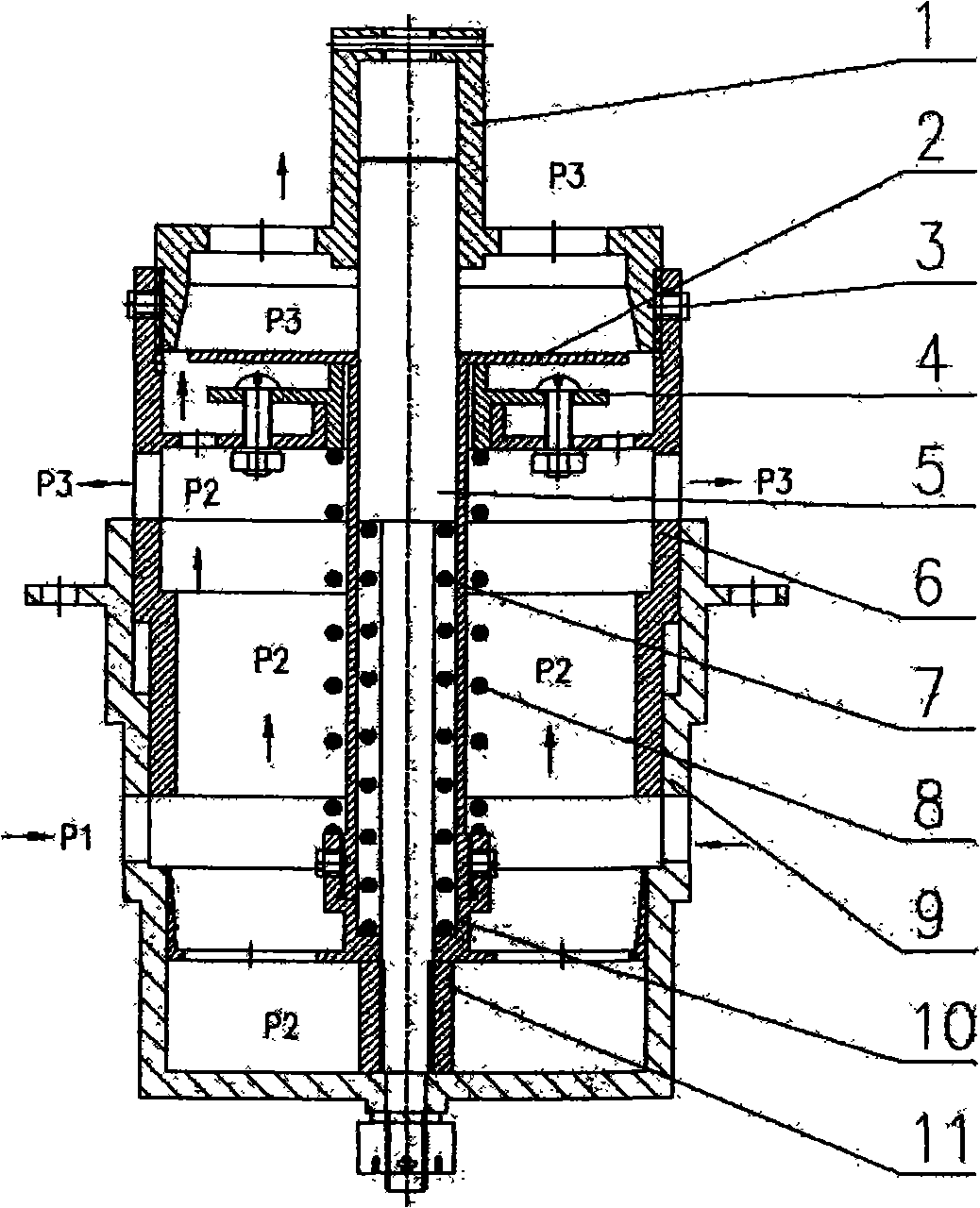
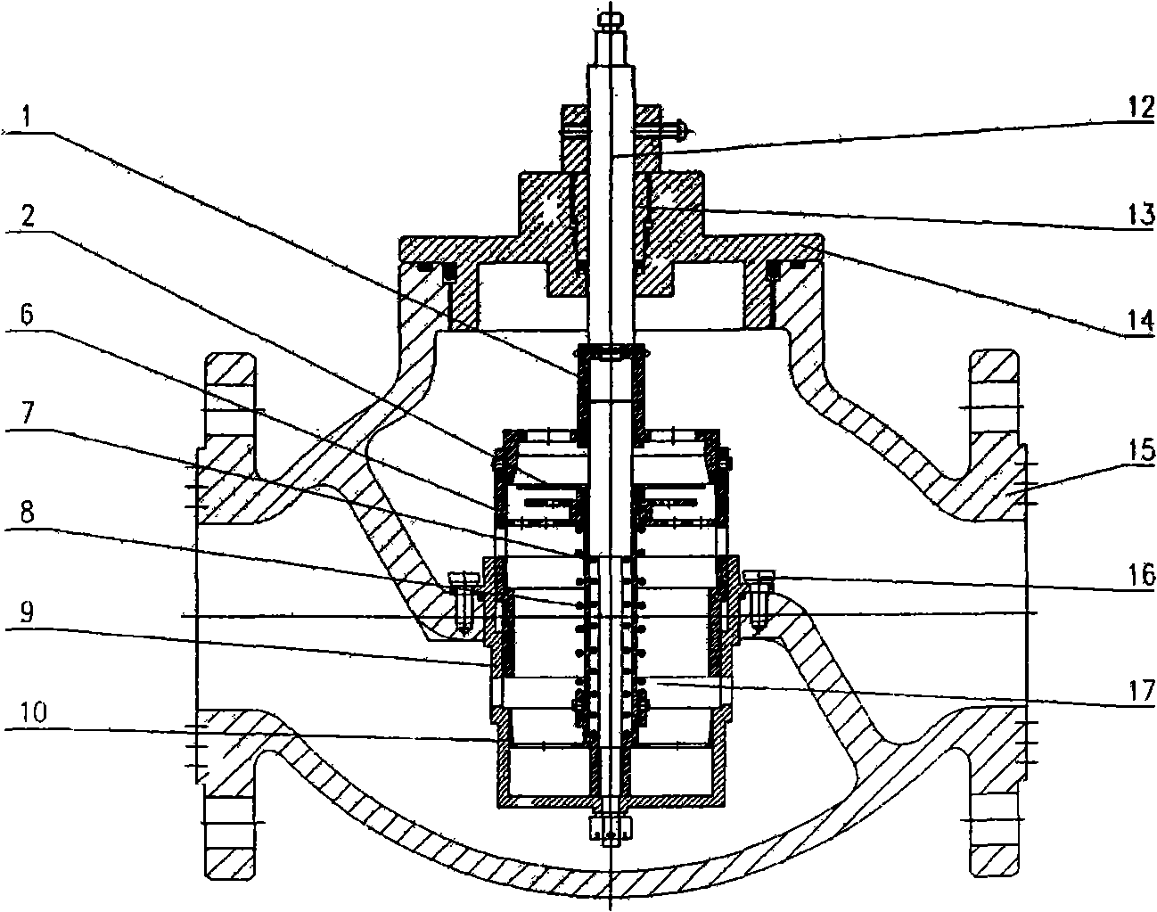
[0022] figure 1 Among them, the dynamic flow balance valve with a built-in spool type includes a valve body 15, a spool 17, an upper sealing cover 14, a sealing gland 13, a connecting rod 12, and fastening screws 16. The valve bladder 17 is fixed inside the valve body 15 by fastening screws 16, and can be disassembled separately. The upper sealing cover 14 and the sealing gland 13 are extended through the connecting rod 12, and the opening of the valve bladder 17 can be adjusted by adjusting the connecting rod 12. . The spool 17 of this valve is fixed in the inner cavity of the valve body 15 with fastening screws 16, and the extension connecting rod 12 is used to adjust the opening of the valve. There is an upper sealing cover 14 on it that is tightly sealed with the valve body 15 by threads. Utilize the sealing gland 13 and the V-shaped rubber ring t...


PUM


Abstract

The invention discloses an adjustable dynamic flow balance valve with an internal lining, which has the function of the dynamic flow balance valve and can adjust the flow capacity passing the valve within certain pressure difference according to the requirement. The invention comprises a valve body, the internal detachable valve lining, a gland cover, a connecting rod and an actuator. The valve lining is fixedly mounted inside the valve body. The connecting rod connected with the valve lining drills through the upper gland cover to be connected with an adjusting handle or the actuator. The opening degree of the valve is controlled for adjusting the flow capacity. The valve lining comprises a pressure sensing board, a pressure regulating slide sleeve, an internal spring, an external spring, the upper end cap with the correction conical surface of the valve lining, a current regulating cylinder body and a lower cylinder body. The invention has the advantages of large current regulating range, large flow capacity, high control precision, broad working pressure difference, convenient assembly, long service life, detachable valve lining and low manufacture cost. The invention can be applied to the central air conditioner, the water system of the heating network, petroleum industry, chemical industry and electric power plant, fundamentally solving the problem of hydraulic disorder and meeting the requirement of flow control.

Description

technical field [0001] The invention relates to a flow control valve, in particular to a high-precision built-in spool type adjustable dynamic flow balance valve. Background technique [0002] The phenomenon of hydraulic imbalance commonly existing in the fluid transmission and distribution pipeline network will bring the following hazards: (1) The actual flow rate does not match the design flow rate, which will affect the working effect of the pipeline network. For example, in the heating and central air-conditioning water system, due to the phenomenon of hydraulic imbalance, the terminal flow is too small or too large, resulting in uneven heating and cooling, which directly affects the heating and air-conditioning effect and causes customer complaints. (2) It can cause damage to pipe network equipment, cause failure, and serious accidents. Excessive flow will have a greater impact on pipelines and equipment, and generate vibration and noise, which will affect the life of ...

Claims


Application Information

Patent Timeline
Patent Type & Authority Applications(China)
IPC IPC(8): F16K17/22F16K17/36
Inventor 郭健翔张新华史乃川
Owner JINAN ANGLE TECH DEV CO LTD
Why Eureka
Try Eureka