Three-layer combined optical film piece

An optical film, composite technology, applied in optics, nonlinear optics, layered products, etc., can solve the problems of scrap, loss, waste and other problems of four films, and achieve reliable and stable quality, material saving, convenient production and operation Effect

Inactive Publication Date: 2008-09-24
普胜科技电子(昆山)有限公司
View PDF0 Cites 15 Cited by
  • Summary
  • Abstract
  • Description
  • Claims
  • Application Information

AI Technical Summary

Problems solved by technology

Taking the 2.8-inch TFT backlight as an example, the most difficult part of the process is the lamination of the four films on the front. Press the order of the diffusion film, the lower prism film, the upper prism

Method used


Image

  • Three-layer combined optical film piece
  • Three-layer combined optical film piece
  • Three-layer combined optical film piece

Examples


Embodiment 1

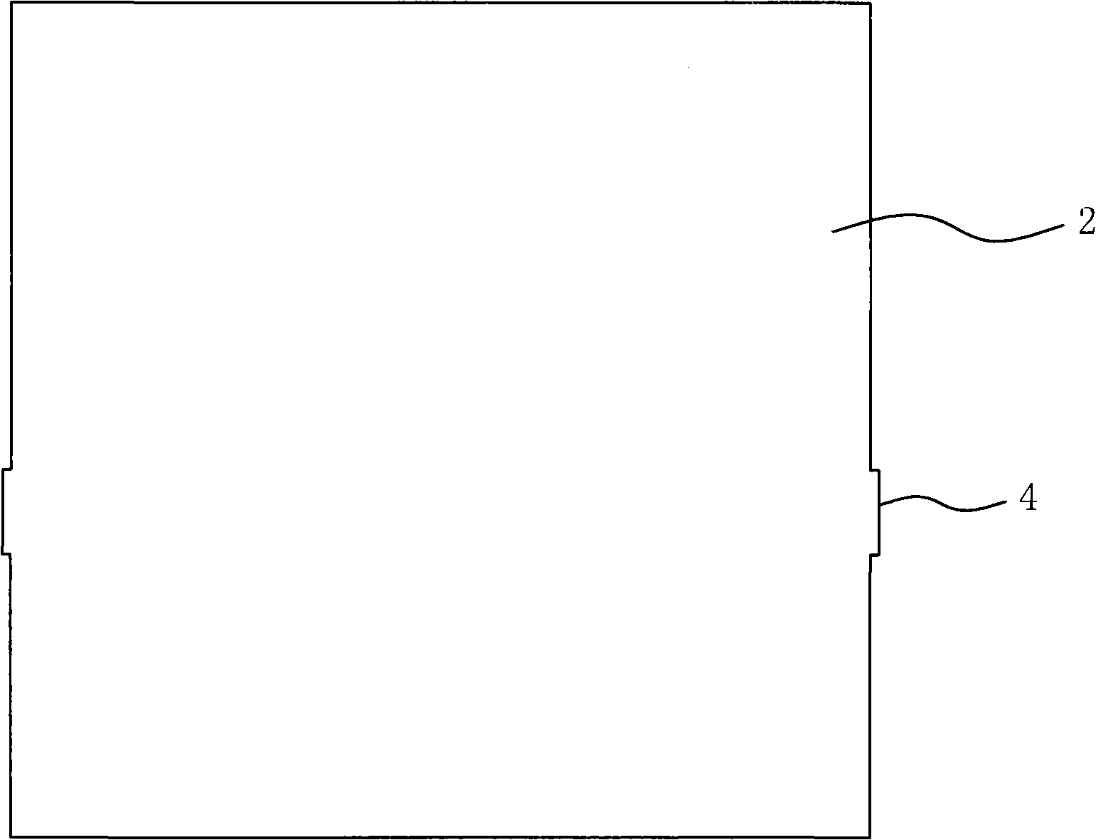
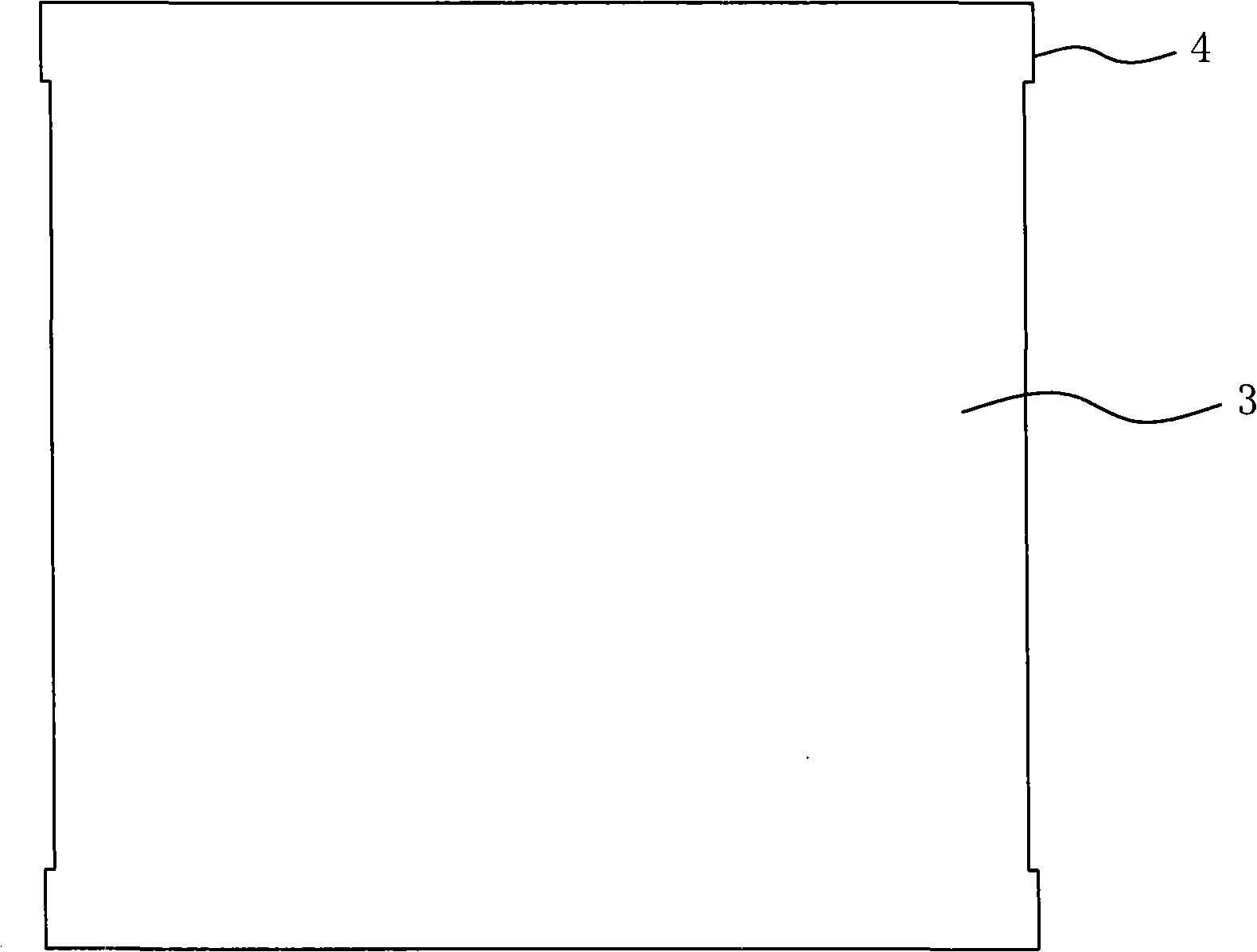
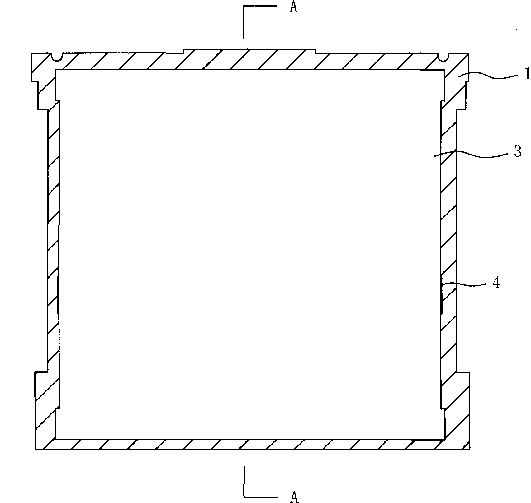
[0030] Embodiment one: see attached figure 1 To attach Figure 6 As shown, a three-layer composite optical film includes two layers of optical film layers, two layers of protective film 6 and a light-shielding double-sided adhesive layer 1, and the composite optical film is composed of the first protective film, the first protective film, The light-shielding double-sided adhesive layer, the first optical film layer 2, the second optical film layer 3 and the second protective film are sequentially stacked, and a light-transmitting part 5 is arranged in the middle of the light-shielding double-sided adhesive layer. The film layer is larger than the light-transmitting part but smaller than the second optical film layer, and the second optical film layer is larger than the first optical film layer but smaller than the light-shielding double-sided adhesive layer.

[0031] In the process of processing, the original three separate diaphragms are composited together by automatic equi...

Embodiment 2

[0032] Embodiment two: a kind of three-layer composite optical film, comprising two layers of optical film layers, two layers of protective film and light-shielding double-sided adhesive layer, the first optical film layer is a prism sheet, and the second optical film layer is Prism sheet. The composite optical film is composed of a first protective film, a light-shielding double-sided adhesive layer, a prism sheet, a prism sheet and a second protective film in sequence from outside to inside, and a light-transmitting part is opened in the middle of the light-shielding double-sided adhesive layer. The first optical film layer is larger than the light-transmitting part but smaller than the second optical film layer, and the second optical film layer is larger than the first optical film layer but smaller than the light-shielding double-sided adhesive layer.

Embodiment 3

[0033] Embodiment 3: The structure is similar to Embodiment 1, wherein the first optical film layer is a diffusion sheet, and the second optical film layer is a diffusion sheet.

[0034] Embodiment 3: The structure is similar to Embodiment 1, wherein the first optical film layer is a prism sheet, and the second optical film layer is a diffusion sheet.


PUM


Abstract

The invention discloses a composite optical membrane which comprises protecting films, optical membrane layers and a shading double-side adhesive tape layer, and the surrounding of the shading double-side adhesive tape layer is an annular stickiness part with the middle forming a transparent part. The invention is characterized in that: the hierarchical structure of the composite optical membrane consists of a first protecting film, the shading double-side adhesive tape layer, a first optical membrane layer, a second optical membrane layer and a second protecting film which are orderly overlapped. The first optical membrane layer is larger than the transparent part but less than the second optical membrane layer; and the surrounding is jointed with the stickiness part. The second optical membrane layer is less than the shading double-side adhesive tape layer, and the surrounding part of the second optical membrane layer exceeding the first optical membrane layer is jointed with the stickiness part of the shading double-side adhesive tape layer. The invention uses the stickiness of the shading double-side adhesive tape layer to directly compound each layer of membrane together by an automatic processing device, which is different from prior complex production process, ensures the more reliable performance of a backlight module and improves the production efficiency.

Description

technical field [0001] The invention relates to an optical element combination, in particular to a component of a backlight module used in a liquid crystal display, that is, a composite optical film. Background technique [0002] With the increasing development of social economy, digital tools such as computers, mobile phones, digital cameras, and video cameras are more widely used. These digital tools are generally equipped with display screens to make human-machine communication easier for users to operate more conveniently. , to bring more convenience to the user's operation. In recent years, most of the display screens of digital tools such as computers, mobile phones, digital cameras, and video cameras use liquid crystal display (Liquid Crystal Display, LCD) panels. A backlight module must be provided under the LCD panel to provide the surface light source required by the LCD panel, so that it can obtain sufficient brightness and contrast, and then realize the display ...

Claims


Application Information

Patent Timeline
IPC IPC(8): G02F1/13357B32B7/02G02F1/1335
Inventor 郑金泰
Owner 普胜科技电子(昆山)有限公司
Why Eureka
Try Eureka