
Modeling method of moment-limited hydraulic coupler-driven complex mechanical system

A technology for hydraulic couplings and mechanical systems, which is applied in the fields of instrumentation, aerodynamic improvement, special data processing applications, etc., and can solve the problems of incomplete matching, neglect, affecting the accuracy, correctness and smooth implementation of complex mechanical systems. , to achieve the effect of improving the accuracy

Inactive Publication Date: 2008-09-24
SHANGHAI NORMAL UNIVERSITY
View PDF0 Cites 3 Cited by
  • Summary
  • Abstract
  • Description
  • Claims
  • Application Information

AI Technical Summary

Problems solved by technology

[0007] As a prior art method, the original characteristic curve of the hydraulic coupling is used to directly excite the mechanical system. Since the original characteristic curve of the hydraulic coupling considers that the speed of the motor and the pump wheel has reached a certain stable speed, this calculation method ignores the motor and the pump wheel. During the transition process of the pump impeller speed increasing from zero to a certain stable speed, the calculated results are not completely consistent with the actual situation, which will affect the accuracy, correctness and smooth implementation of the design of the entire complex mechanical system

Method used


Image

  • Modeling method of moment-limited hydraulic coupler-driven complex mechanical system
  • Modeling method of moment-limited hydraulic coupler-driven complex mechanical system
  • Modeling method of moment-limited hydraulic coupler-driven complex mechanical system

Examples


Embodiment Construction

[0034] The specific embodiment of the present invention will be further described below in conjunction with accompanying drawing:

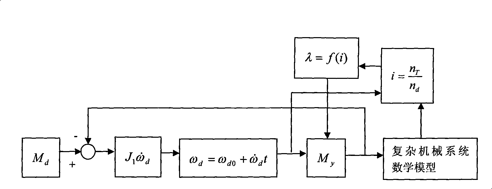
[0035] 1) First, in the initial stage, that is, when the motor is just energized, it generates the motor output torque M d ;

[0036] 2) Secondly, in the initial stage, the hydraulic coupling pump wheel has an initial output torque M y ;

[0037] 3) According to the formula M d - M y = J 1 ω · d and ω d = ω d 0 + ω · d Δt The angular acceleration, angular velocity and rotational speed of the motor and the pump wheel of the hydraulic coupling can be calc...


PUM


Abstract

The invention relates to a modeling method related to a hydraulic coupler in a mechanical engineering field, in particular to a modeling method for a torque limited hydraulic coupler to drive a complex mechanical system. The modeling method for the torque limited hydraulic coupler to driving drive the complex mechanical system separates the mechanical system into two independent parts for the respective modeling and respectively treats a pump wheel and a turbine wheel of the hydraulic coupler. One independent part is that a motor is connected with the pump wheel of the hydraulic coupler and the other independent part is that the turbine wheel of the hydraulic coupler is connected with the mechanical system. Respective motion equations are constructed separately and motion amounts in the mechanical system are calculated according to the two equations. The modeling method of the invention avoids errors which are brought from a traditional direct excitation of an original characteristic curve on the mechanical system, thus leading to that the proposal design accords more correctly and comprehensively with the practical state of the mechanical system, and the correctness, the precision and the implementation efficiency of the design planning work of the whole mechanical system are improved.

Description

(1) Technical field [0001] The invention relates to a modeling method related to a hydraulic coupling in the field of mechanical engineering, in particular to a modeling method for a moment-limited hydraulic coupling driving a complex mechanical system. (2) Background technology [0002] The torque-limiting hydraulic coupling is a non-rigid coupling with liquid as the working medium, also known as the hydraulic coupling. It mainly consists of active part and passive part. The active part includes the rear auxiliary chamber, the front half coupling, the rear half coupling, the elastic block, the pump wheel and the casing, and the driven part mainly includes the shaft and the turbine wheel. The active part is connected with the prime mover, and the passive part is connected with the working machine. [0003] The pump wheel and the turbine wheel of the hydraulic coupling form a closed working chamber that can circulate the liquid. The pump wheel is installed on the input shaf...

Claims


Application Information

Patent Timeline
Patent Type & Authority Applications(China)
IPC IPC(8): G06F17/50
CPCY02T10/82
Inventor 李光布
Owner SHANGHAI NORMAL UNIVERSITY
Learn More