
Air dehumidification and solution regenerating device

A technology for solution regeneration and air dehumidification, which is applied in air conditioning systems, space heating and ventilation, household heating, etc., and can solve problems such as complex production of internally cooled packed towers, deteriorating dehumidification or regeneration performance, and affecting the normal operation of dehumidification towers, etc. , to achieve the effect of improving heat and mass exchange performance, good chemical stability, and improving dehumidification effect

Inactive Publication Date: 2010-06-09
UNIV OF SHANGHAI FOR SCI & TECH
View PDF1 Cites 0 Cited by
  • Summary
  • Abstract
  • Description
  • Claims
  • Application Information

AI Technical Summary

Problems solved by technology

[0003] The invention discloses an air dehumidification and solution regeneration device, the purpose of which is to overcome the temperature rise of the solution in the dehumidification process of the existing adiabatic packing dehumidification tower and the decrease of the dehumidification or regeneration performance caused by the decrease of the solution in the regeneration process; The fabrication of the cold packed tower is complicated, and the flow resistance is large, which leads to an increase in the power consumption of the solution pump, which causes air resistance during the operation of the packed tower and causes liquid flooding, which affects the normal operation of the dehumidification tower, etc.

Method used


Image

  • Air dehumidification and solution regenerating device
  • Air dehumidification and solution regenerating device
  • Air dehumidification and solution regenerating device

Examples


Embodiment Construction

[0012] The present invention will be described in further detail below in conjunction with accompanying drawing and embodiment, but present embodiment is not intended to limit the present invention, and every adopt similar structure of the present invention and similar change thereof, all should be included in the protection scope of the present invention.

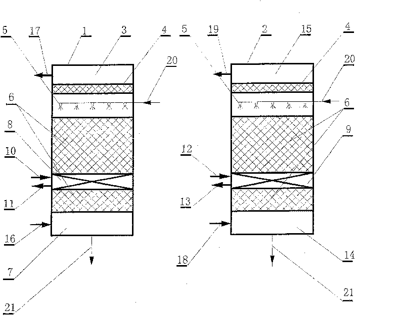
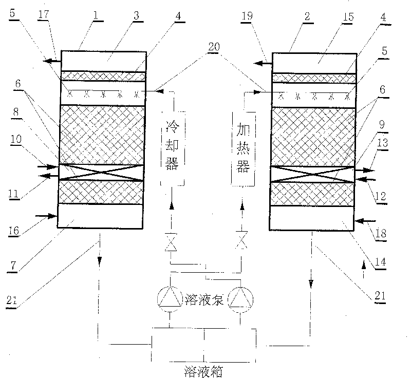
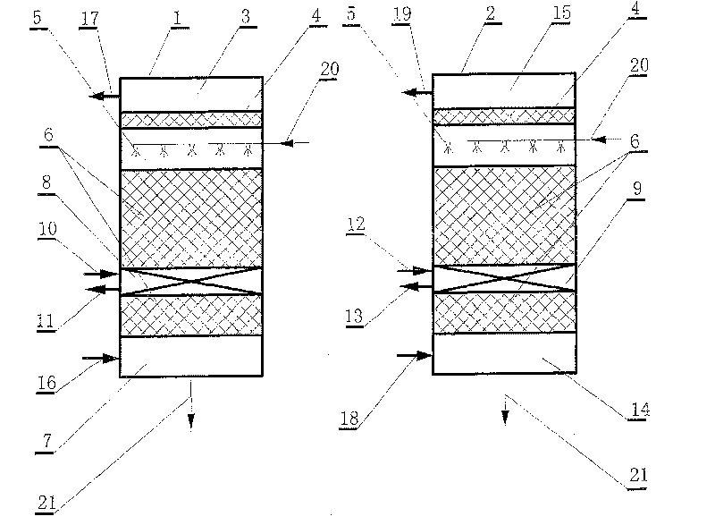
[0013] Air dehumidification and solution regeneration devices such as figure 1 As shown, the structure of dehumidification tower 1 from top to bottom is: dry air layer 3, demister 4, liquid distributor 5, packing 6 and air layer 7 to be treated, and the structure of regeneration tower 2 is from top to bottom: : outlet air layer 15, demister 4, liquid distributor 5, filler 6 and inlet air layer 14, characterized in that: upper and lower layers of filler 6 are arranged between the liquid distributor 5 of dehumidification tower 1 and the air layer 7 to be treated The dehumidification tower 1 is provided with a cooling coil 8 ...


PUM


Abstract

The present invention relates to an air dehumidifying and solution regenerative device, the structure of the dehumidifying tower from top to bottom is: a drying air space, a foam destroyer, a cloth liquid machine, a filling and an inlet air space. The upper and lower layer filling are placed between the cloth liquid machine of the dehumidifying tower and the air space to processed; a cooling coilis placed between the upper and lower layer filling, the inlet and outlet of the chilled water of the cooling coil is placed at the lateral wall of the dehumidifying tower connecting the refrigeratingmechanism by the piping; the place between the cloth liquid machine of the regeneration tower and the inlet air space has the upper and lower layer filling; the place between the upper and lower layer filling has a heating coil pipe in which the inlet of the heating water and the export of the heating water are placed at the lateral wall of the regeneration tower, and connecting the heater by thepiping. The present invention has simple structure, convenient manufacturing, avoiding the continuous temperature rising of the dehumidifying solution and the continuous temperature reduction of theregenerating solution, improving the dehumidifying effect and regeneration effect notability.

Description

technical field [0001] The invention relates to an air dehumidification and solution regeneration device used in the field of refrigeration and air-conditioning engineering, in particular to a dehumidification and air-conditioning device that uses a hygroscopic agent solution to dehumidify the air and uses air to regenerate the solution. Technical improvements of packed towers and internally cooled packed towers. Background technique [0002] In the liquid dehumidification air-conditioning system, the solution regeneration device and the air dehumidification device are the core parts of the liquid dehumidification air-conditioning system, and are the main places for heat and mass exchange between the air and the hygroscopic solution. The design of the regenerator and dehumidifier is related to the entire dehumidification. Performance of the air conditioning system. According to the contact mode in the process of heat and mass exchange between humid air and liquid hygroscopi...

Claims


Application Information

Patent Timeline
Patent Type & Authority Patents(China)
IPC IPC(8): F24F3/14
Inventor 王瑾柳建华刘金松安守超陈军李村男张广丽
Owner UNIV OF SHANGHAI FOR SCI & TECH
Learn More