Passive bias optical fiber gyroscope and current sensor

An optical fiber sensor and sensor technology, which is applied in the coupling of Sagnac effect gyroscopes and optical waveguides, etc., can solve the problem of the sensitivity of the short section of the optical fiber, the complicated structure and layout of the interference optical path, and the single-mode fiber does not have the ability to maintain the polarization state of the light. And other issues

Inactive Publication Date: 2008-10-01
黄宏嘉
View PDF5 Cites 19 Cited by
  • Summary
  • Abstract
  • Description
  • Claims
  • Application Information

AI Technical Summary

Problems solved by technology

The main defect of the sensor structure thus constituted is that the single-mode fiber does not have the function of maintaining the polarization state of light, so the optical fiber interference sensor comprising a 3×3 single-mode fiber coupler cannot work stably, so that it cannot be practical
Obviously, the unadvisable point of the former method is that the structure and layout of the interference optical path become very complicated. The fundamental difficulty of the latter method is that the short section of optical fiber is a very sensitive element in terms of physical nature.

Method used


Image

  • Passive bias optical fiber gyroscope and current sensor
  • Passive bias optical fiber gyroscope and current sensor
  • Passive bias optical fiber gyroscope and current sensor

Examples


Embodiment Construction

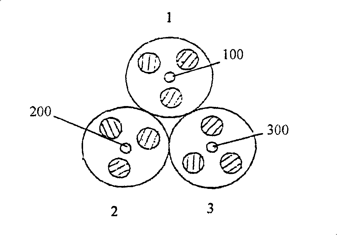
[0025] One embodiment of the present invention is a full "circle" PM fiber sensor structure that utilizes a 3 x 3 "circle" PM fiber coupler as the passive biasing device, such as figure 1 shown.

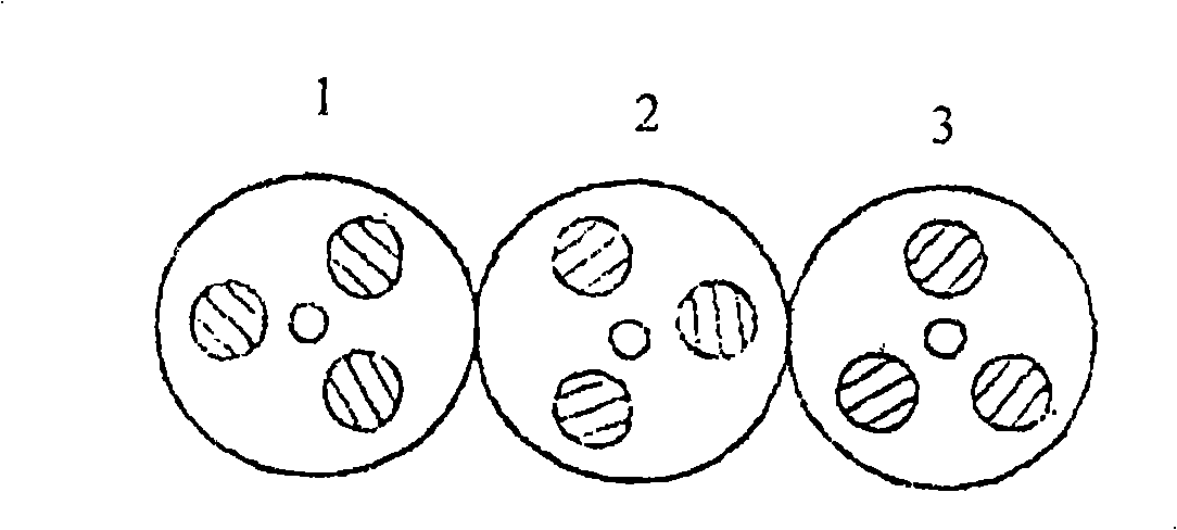
[0026] The cross-sectional structure of the 3×3 “circle” polarization-maintaining fiber coupler is shown in Figure 2a . For the detailed technical description of the "circle" polarization maintaining fiber, please refer to the inventor's previous invention patents: China ZL88107839.X, ZL01132102.4 and US 5,452,394. Figure 2a Among them, the numbers 1, 2, and 3 indicate the cross-sections of three "circle" polarization-maintaining fibers, and 100, 200, and 300 indicate the cores of the corresponding fibers; the three circles with diagonal lines symmetrical to the core outside each core represent A set of stress regions that rotate around the core during the drawing process to produce circular birefringence in the finished fiber. The cores of the three optical fibers forming the 3...


PUM


Abstract

In one of embodiments of passive polarizing fiber optic gyroscope and current sensor, the core is a 3X3 ''round''polarization maintaining optic fiber coupler composed of ''round'' polarization maintaining fiber coupler. The coupler realizes light splitting and passive polarization effects simultaneously in Sagnac interference sensor optic fiber loop. A variable 3X3 hybrid optic fiber coupler is composed by two linear polarization maintaining optic fibers and a regular single mode optic fiber, wherein the tail fiber of the two linear polarization maintaining optic fibers are connected in interference optic fiber loop based on the linear polarization maintaining optic fiber, the two ends of the single mode optic fiber are cut into short sections by diagonal angles, in order to form matching end face on the two ends. In other embodiment of the passive polarizing fiber sensor, the core is an integrated Faraday rotator, comprising accurate magnetic-optic 45 degree rotation unit, of which one end is connected with a one-quarter glass of ''zero-to-rapid'' optic fiber, other end is connected with a one-quarter glass of ''rapid-to-zero'' optic fiber. The main merit of the passive polarization comprises: simple structure, working stability without manually tuning.

Description

technical field [0001] The present invention relates to optical fiber sensors, optical fiber interference loops, Sagnac interferometers, gyroscopes, current and magnetic field sensors, optical fiber Sagnac interferometers, passive bias optical fiber gyroscopes, passive bias optical fiber current sensors, and 3×3 “circle” polarization-maintaining optical fibers Coupler, 3×3 line polarization maintaining fiber coupler, fine optics magneto-optical Faraday rotator. Background technique [0002] The optical fiber sensor based on the Sagnac interference optical path in the present invention mainly refers to two types of sensors, that is, the rotational speed sensor based on the Sagnac effect, commonly known as a gyroscope, and the current or magnetic field sensor based on the Faraday effect. Both effects are non-reciprocal, and thus the two fields of research, gyroscopes and current sensors, have long been developed in parallel on a common basis utilizing the same Sagnac interfero...

Claims


Application Information

Patent Timeline
Patent Type & Authority Applications(China)
IPC IPC(8): G01C19/64G02B6/28
Inventor 黄宏嘉
Owner 黄宏嘉
Why Eureka
Try Eureka