Shearing type large size material damping testing device
A testing device and material damping technology, applied in measurement devices, analytical materials, material inspection products, etc., can solve the problem of inability to test the shear damping characteristics of large-sized materials, break through the bottleneck that the damping characteristics cannot be accurately measured, and improve the displacement The effect of measurement accuracy and simple device structure
- Summary
- Abstract
- Description
- Claims
- Application Information
AI Technical Summary
Problems solved by technology
Method used
Image

Examples
specific Embodiment approach 1
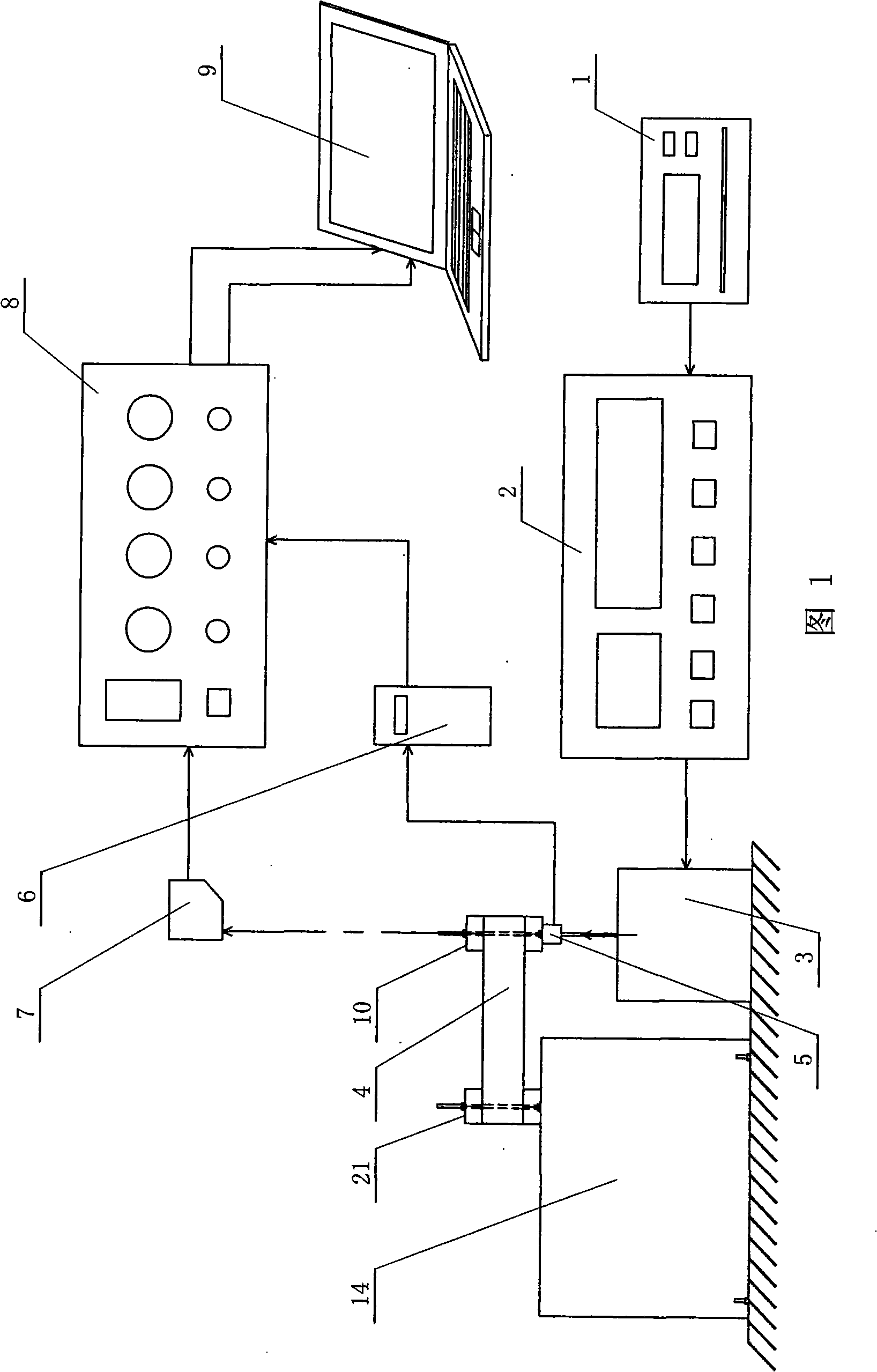
[0007] Specific embodiment one: illustrate this embodiment in conjunction with Fig. 1, the damping test device of this embodiment is made up of excitation system, measurement system, loading head 10, fixing kit 21 and base 14; Described excitation system is made up of signal generator 1, power An amplifier 2 and an electromagnetic exciter 3 are formed, and the measurement system is composed of a piezoelectric force sensor 5, a laser displacement sensor 7, a charge amplifier 6, a voltage amplifier 8, and a computer data collector 9. The piezoelectric force sensor 5 The two input ends of the electromagnetic exciter 3 and the lower end surface of the loading head 10 are respectively connected to realize the data acquisition of the tension pressure, and the output end of the piezoelectric force sensor 5 is connected to the input end of the charge amplifier 6, so Directly above the electromagnetic exciter 3 is provided with a laser displacement sensor 7, the output end of the laser ...
specific Embodiment approach 2
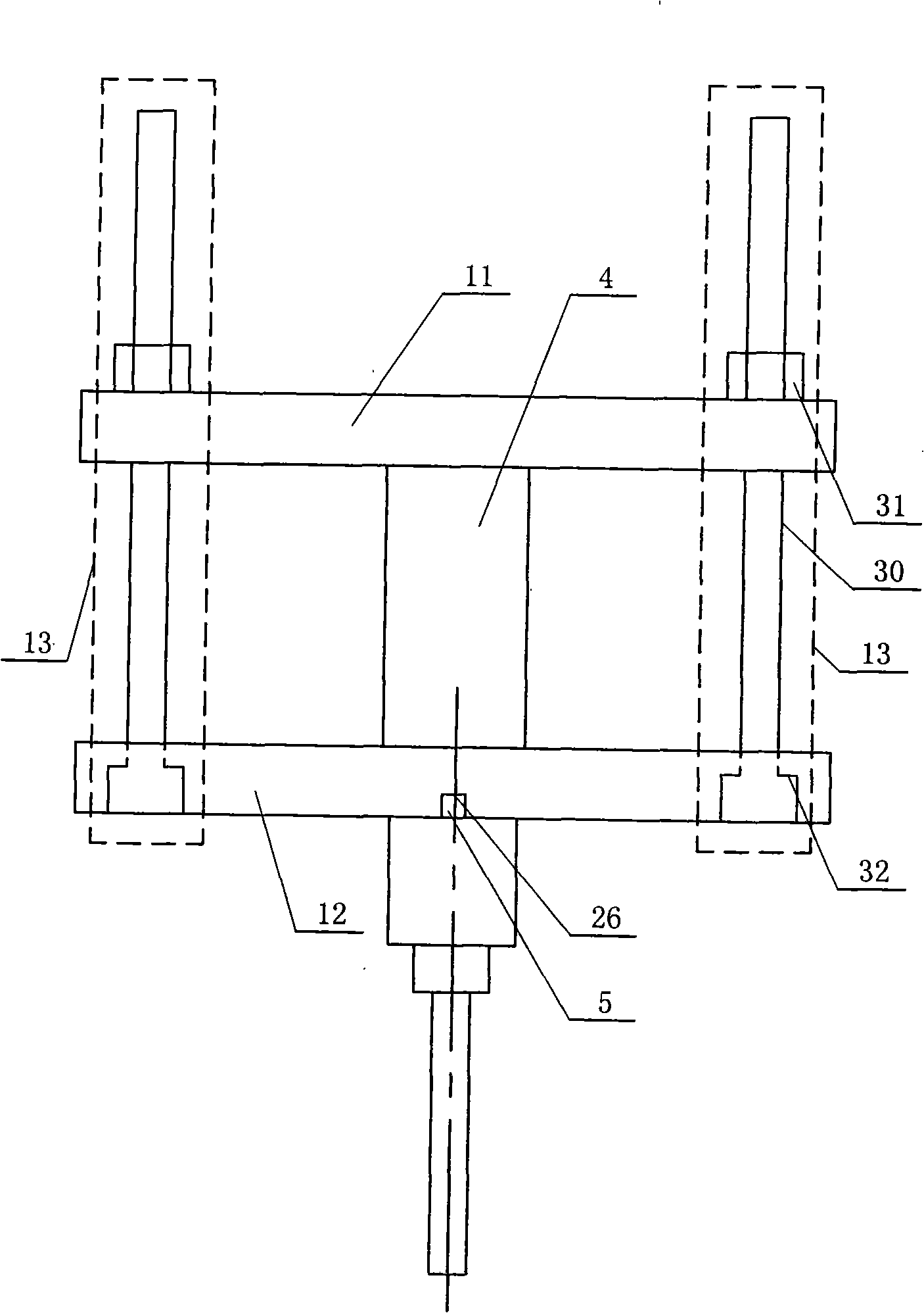
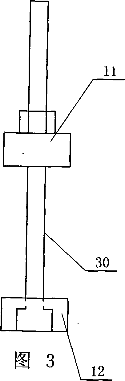
[0011] Specific Embodiment 2: This embodiment is described with reference to FIGS. 1 to 3 . The loading head 10 of this embodiment is composed of a first upper beam 11 , a second lower beam 12 , and two first connectors 13 ; the first upper The beam 11 is arranged on the first lower beam 12, the two ends of the first upper beam 11 and the first lower beam 12 are respectively connected by a first connecting piece 13, the lower end surface of the first lower beam 12 is provided with a groove 26, The upper end of the piezoelectric force sensor 5 is installed in the groove 26 of the lower end surface of the first lower beam 12, and the first connecting piece 13 is composed of a screw rod 30 and a nut 31; the big end of the screw rod 30 is installed at the second In the shoulder holes 32 of the lower end faces of the two lower beams 12. Such an arrangement facilitates the installation of the force sensor 5 and the first lower beam 12 . Other components and connections are the same...
specific Embodiment approach 3
[0012] Specific embodiment three: in conjunction with Fig. 1, Figure 4 , Figure 5 To illustrate this embodiment, the fixing kit 21 of this embodiment is composed of a second upper beam 22, a second lower beam 23, two second connectors 24, and two third connectors 25; the second upper beam 22 is set On the second lower beam 23, the two ends of the second upper beam 22 and the second lower beam 23 are respectively connected by a second connecting piece 24, and the second lower beam 23 is arranged on the base 14, and the second lower beam 23 The two ends of the base 14 are respectively connected by a third connecting piece 25 . Such setting can facilitate the adjustment of the height of the member 4 to be measured. Other components and connections are the same as those in the first embodiment.
PUM
| Property | Measurement | Unit |
|---|---|---|
| area | aaaaa | aaaaa |
| length | aaaaa | aaaaa |
Abstract
Description
Claims
Application Information
 - R&D
- Intellectual Property
- Life Sciences
- Materials
- Tech Scout
- Unparalleled Data Quality
- Higher Quality Content
- 60% Fewer Hallucinations
Browse by: Latest US Patents, China's latest patents, Technical Efficacy Thesaurus, Application Domain, Technology Topic, Popular Technical Reports.
© 2025 PatSnap. All rights reserved.Legal|Privacy policy|Modern Slavery Act Transparency Statement|Sitemap|About US| Contact US: help@patsnap.com