Spectacle lens chamfering machine

A technology for chamfering machines and spectacle lenses, which is applied to machine tools, grinders, abrasives and other directions suitable for grinding the edges of workpieces, can solve the problems of easy cutting hands, high price, inconvenient maintenance, etc., and achieves convenient chamfering, easy learning, Affordable price and easy maintenance

Inactive Publication Date: 2008-10-15
陆雄杰
View PDF2 Cites 8 Cited by
  • Summary
  • Abstract
  • Description
  • Claims
  • Application Information

AI Technical Summary

Problems solved by technology

[0002] In the glasses industry currently on the market, after the glasses lenses are processed and shaped, sharp corners will be formed around the two sides of the glasses lenses, which is easy to cut hands. Usually, the sharp corners around the lenses are manually removed on the grinding wheel with a hand grinder, but Due to the difference between the experience of the manual operator and the hand grinder, the chamfering parts around the two sides of the lens are often large and small, which is difficult to grasp, making the chamfering of the lens uneven, and our glasses are composed of two lenses. For a pair of glasses, it is even more difficult to pour the two lenses into the same uniform angle. It requires a high level of skill for the manual operator. It usually takes about two years to develop a more proficient skill.
The chamfering device imported from abroad is an integrated device, such as the invention patent 01117260.6 "Lens peripheral processing method of spectacle lens, lens peripheral processing device and lens" and 200410034604.4 "Chamfering processing method of spectacle lens" by Topcon Co., Ltd. and chamfering processing device” discloses an integrated chamfering processing device, but the above-mentioned device is expensive, and different programs must be selected for lenses of different materials, the operation is more complicated, and the structure is also complicated, and maintenance is inconvenient. use the device

Method used


Image

  • Spectacle lens chamfering machine
  • Spectacle lens chamfering machine

Examples


Embodiment Construction

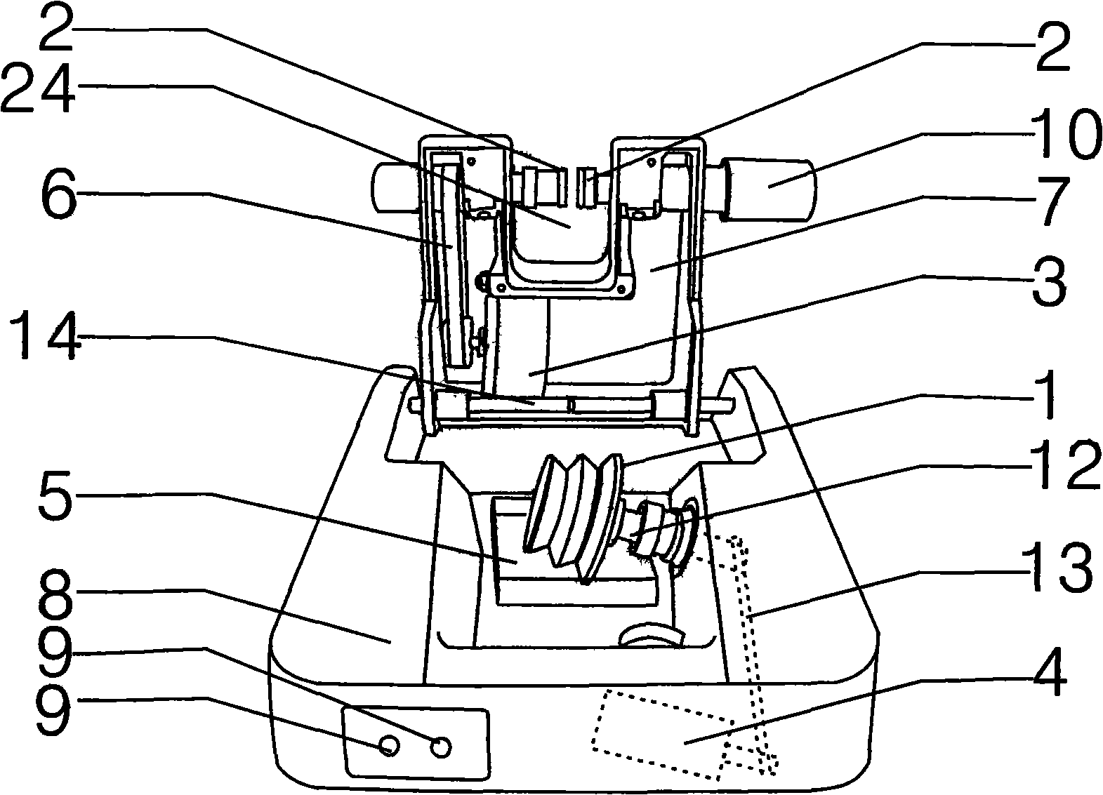
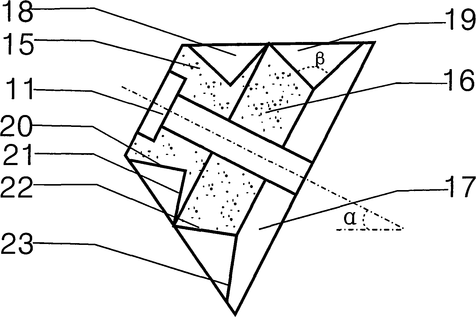
[0019] like figure 1 and figure 2 As shown, the spectacle lens chamfering machine includes a chamfering grinding wheel combination 1, two lens chucks 2, a motor 3, a grinding wheel motor 4, a water tank 5, a transmission belt 6, a machine head 7, a casing 8 and a switch 9, the two Two lens chucks 2 are fixed on the top of the machine head 7, and the motor 3 is connected with the outer end of one lens chuck 2 through the transmission belt 6, and the outer end of the other lens chuck 2 is provided with a clamping knob 10, and the chamfering The grinding wheel assembly 1 is fixed on the rotating shaft 12 of the casing through a nut 11, and the rotating shaft 12 is connected with the grinding wheel motor 4 through the transmission belt II13, and the transmission belt II13 and the grinding wheel motor 4 are all arranged at the bottom of the casing 8, and the machine head 7 is connected to the grinding wheel motor 4. The casing 8 is movably connected by a sliding rod 14 fixed on t...


PUM


Abstract

The invention relates to a chamfering machine for spectacle lens. The chamfering machine comprises a chamfer grinding wheel combination, two lens clamping chucks, a motor, a grinding wheel motor, a flume, a driving belt, a machine head, a casing and a switch. The two lens clamping chucks are fixed at the top of the machine head; the rear end of one lens clamping chuck is connected with the motor and a clamping nut is arranged on the rear end of the other lens clamping chuck. The chamfering grinding wheel is fixed on the casing shaft through nuts, the shaft is connected with the grinding wheel motor through a second driving belt, and the second driving belt and the grinding wheel motor are both arranged at the bottom of the casing; a slide rod is arranged on the upper end of the casing, and the machine head is movably sleeved on the slide rod. An inclined angle Alpha between the shaft and the horizontal direction is 10-20 DEG; the chamfering grinding wheel is formed by a combination of a first grinding wheel, a second grinding wheel and a rag wheel engaged mutually, and is fixed on the shaft to form a rimmed lens special notch and a rimless lens special notch. By adopting the inventive structure, the chamfering machine has the advantages that the chamfering operation is convenient and easy to learn, the structure is simple, the maintenance is convenient and the price is moderate.

Description

technical field [0001] The invention relates to an edge chamfering mechanism of spectacle lenses, in particular to a spectacle lens chamfering machine. Background technique [0002] In the glasses industry currently on the market, after the glasses lenses are processed and shaped, sharp corners will be formed around the two sides of the glasses lenses, which is easy to cut hands. Usually, the sharp corners around the lenses are manually removed on the grinding wheel with a hand grinder, but Due to the difference between the experience of the manual operator and the hand grinder, the chamfering parts around the two sides of the lens are often large and small, which is difficult to grasp, making the chamfering of the lens uneven, and our glasses are composed of two lenses. For a pair of glasses, it is even more difficult to pour the two lenses into the same uniform angle. It requires a high level of skill for the manual operator. It usually takes about two years to develop a m...

Claims


Application Information

Patent Timeline
Patent Type & Authority Applications(China)
IPC IPC(8): B24B9/14B24D7/18
Inventor 陆雄杰
Owner 陆雄杰
Why Eureka
Try Eureka