Biloded wheel aeration machine under water
An aerator and double impeller technology, applied in water aeration, sustainable biological treatment, water/sludge/sewage treatment, etc., to achieve high oxygenation rate, low noise, and high power efficiency
Inactive Publication Date: 2008-10-15
JIANGSU UNIV
View PDF3 Cites 28 Cited by
- Summary
- Abstract
- Description
- Claims
- Application Information
AI Technical Summary
Problems solved by technology
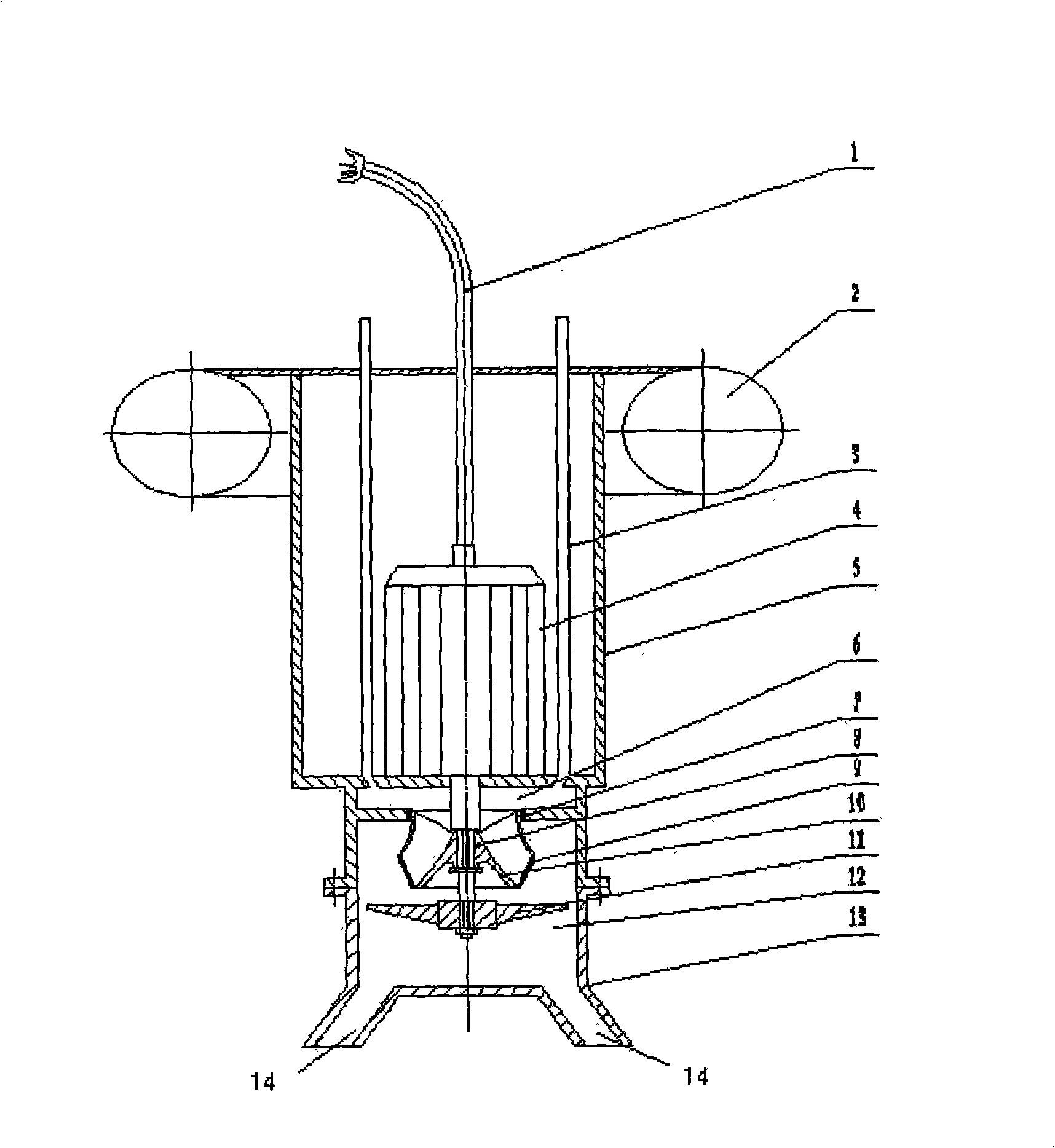
The technical problem to be solved by the present invention is to provide a double-impeller submerged aerator with smaller and more uniform air bubbles, high oxygenation rate and faster oxygenation speed in view of the shortcomings of the current aerators.
Method used
View moreImage
Smart ImageViewing Examples
Examples
Embodiment Construction
Login to View More PUM
 Abstract
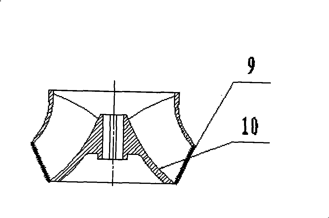
The invention discloses a double-impeller underwater aeration machine which is applied to the underwater aeration oxygenation in the wastewater treatment. A submersible motor (4) drives a wind impeller (10) and a water impeller (11) to rotate at a high speed after being electrified, when rotating at the high speed, the wind impeller (10) sucks the water in an air inlet pipe (3) and an air chest (6) out, negative pressure is formed in the air chest (6), the outside air can enter the air chest (6) along the air inlet pipe (3), and can pass through an impeller outlet arc-shaped baffle (9) under the action of the water impeller (11), so as to be aerated into the water in a micro-bubble way; at the same time, the water flows through the water impeller (11) along with the micro-bubbles under the action of the water impeller (11), the bubbles in the water can be cut so as to be smaller under the stirring of the water impeller, and the air-water mixture turbulently flows in a buffer room (12), so as to enable the air and the water to be more evenly mixed and finally dashed into the wastewater from the diversion outlet (14) of a lower shell (13) at a certain speed, thereby the produced bubbles are smaller and evener, and the aeration oxygenation efficiency is higher.
Description
A double impeller submerged aerator technical field The invention relates to an aeration and oxygenation device in sewage treatment, in particular to a double impeller submerged aerator. Background technique At present, more than 90% of urban sewage and about 50% of industrial organic sewage at home and abroad are treated by activated sludge method. A large amount of dissolved oxygen is needed in the biochemical process of activated sludge treatment of sewage, and aeration and oxygenation have become the core link of biochemical treatment. Aeration devices can be divided into mechanical aeration devices, blast aeration systems, hydraulic shear aeration devices, hydraulic impact aeration devices, etc. The above-mentioned aeration devices are widely used in sewage treatment, but all have their own shortcomings. For mechanical aeration devices, such as the Chinese utility model patent of Patent No. ZL200520135925.3 (CN2837298Y), a kind of inverted umbrella aeration device h...
Claims
Login to View More Application Information
Patent Timeline
 IPC IPC(8): C02F3/12C02F7/00
CPCY02W10/10
Inventor 李维斌吴春笃朱荣生
Owner JIANGSU UNIV
Features
- R&D
- Intellectual Property
- Life Sciences
- Materials
- Tech Scout
- Unparalleled Data Quality
- Higher Quality Content
- 60% Fewer Hallucinations
Learn More Browse by: Latest US Patents, China's latest patents, Technical Efficacy Thesaurus, Application Domain, Technology Topic, Popular Technical Reports.
© 2025 PatSnap. All rights reserved.Legal|Privacy policy|Modern Slavery Act Transparency Statement|Sitemap|About US| Contact US: help@patsnap.com


