
Heat sink assembly

A technology of heat dissipation module and heat dissipation fins, applied in cooling/ventilation/heating transformation, electrical components, electric solid state devices, etc., can solve the problems of affecting the natural convection of fins, low airflow utilization rate of fan 110, etc., to improve heat dissipation The effect of efficiency

Inactive Publication Date: 2008-10-15
FU ZHUN PRECISION IND SHENZHEN +1
View PDF1 Cites 5 Cited by
  • Summary
  • Abstract
  • Description
  • Claims
  • Application Information

AI Technical Summary

Problems solved by technology

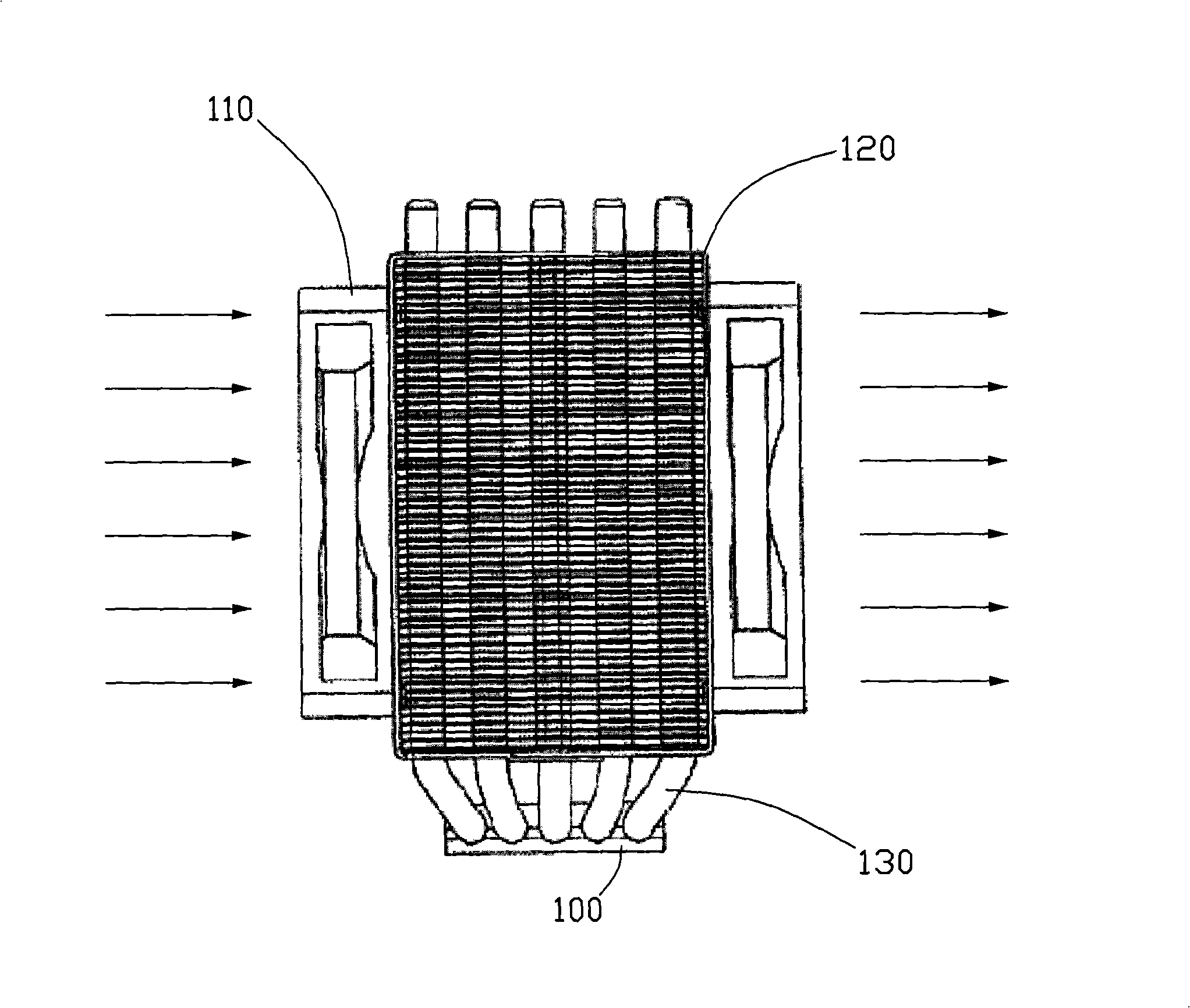
In the aforementioned patent, the airflows produced by the two fans 110 are on the same straight line, and most of the airflows are not fully absorbed by the heat of the fins and are quickly sucked out to the outside by the fans 100. The utilization rate of the airflows of the fans 110 is low; Block 100 parallel, also affects the natural convection of the fins

Method used


Image

  • Heat sink assembly
  • Heat sink assembly
  • Heat sink assembly

Examples


Embodiment Construction

[0016] The heat dissipation module according to the first embodiment of the present invention is used to be installed on heat-generating electronic components such as a central processing unit (not shown in the figure) to dissipate heat.

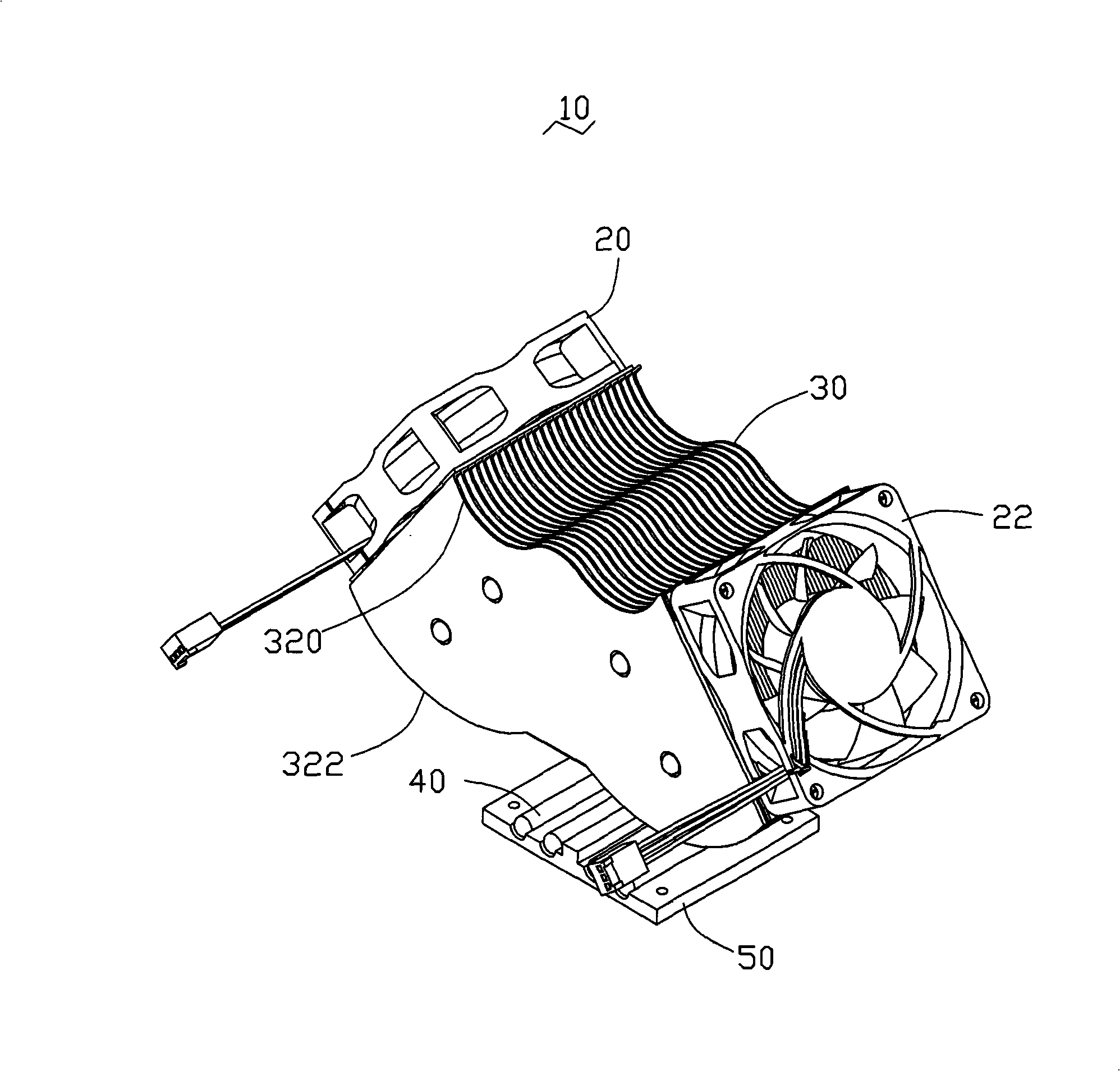
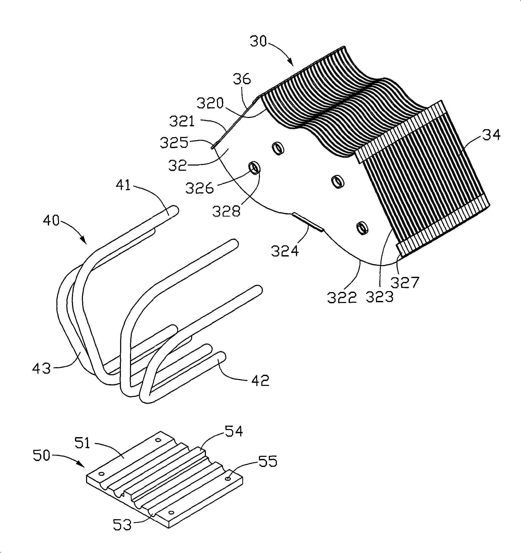
[0017] see Figure 2 to Figure 4 , shows the heat dissipation module 10 of the first embodiment of the present invention. The heat dissipation module 10 includes a heat conduction base 50, a first fin group 30 arranged above the heat conduction base 50 at a certain distance, a plurality of heat pipes 40 connecting the first fin group 30 and the heat conduction base 50, and The first fan 20 and the second fan 22 are arranged on two sides of the first fin set 30 and are inclined relative to each other.

[0018] The heat conduction base 50 is roughly square, and its bottom surface extends downward to form a roughly square bump 52. The lower surface 521 of the bump 52 is used to contact with the heat-generating electronic components; There is ...


PUM


Abstract

The invention provides a heat dissipation module used for the heat dissipation of electronic elements. The heat dissipation module comprises a first group of cooling fins which consists of a plurality of the cooling fins mutually arranged at intervals. A plurality of air channels are formed among the cooling fins, and the two sides of the first group of the cooling fins, which are communicated with the air channel, are respectively provided with a first fan and a second fan. The first fan is inclined relatively to the second fan and all airflow orifices face the electronic elements. The airflow generated by the first fan flows through the first group of the cooling fins and blows to the direction of the electronic elements. The second fan extracts the airflow from the electronic elements and then the airflow is discharged by the first group of the cooling fins. The airflow generated by the heat dissipation module of the invention can directly blow to a high-temperature zone nearby the electronic elements so as to ensure the complete airflow heat dissipation, thus improving the cooling efficiency.

Description

technical field [0001] The invention relates to a cooling module, in particular to a cooling module for cooling electronic components. Background technique [0002] Central processing units and other electronic components will generate a lot of heat during normal operation. If the heat generated is not discharged in time, the operation stability of electronic components will be affected. Therefore, in order to ensure the normal operation of the electronic components, the industry usually installs a cooling module on the electronic components for auxiliary heat dissipation. [0003] Such as figure 1 As shown, Chinese patent application No. 200320103941.5 discloses a heat dissipation module, the heat dissipation module is provided with a fin set 120 at a certain distance above the base 100, and several "U" shaped heat pipes are passed between the fin set 120 and the base 100 130 are connected. The fin group 120 is formed by stacking a plurality of cooling fins parallel to t...

Claims


Application Information

Patent Timeline
IPC IPC(8): H05K7/20H01L23/467
CPCH01L2924/0002
Inventor 吴伟乐陈俊吉
Owner FU ZHUN PRECISION IND SHENZHEN
Learn More