Method of continous annealing/hot-dipping of steel sheet containing silicon and apparatus for continuous annealing/hot-dipping

A technology of hot-dip plating and steel plate, which is applied in the direction of hot-dip plating process, heat treatment furnace, heat treatment equipment, etc., can solve problems such as hindering plating performance, alloying speed reduction, and roller defects in the furnace, so as to achieve excellent coating adhesion, The effect of inhibiting enrichment

Active Publication Date: 2008-10-15
NIPPON STEEL CORP
View PDF2 Cites 32 Cited by
  • Summary
  • Abstract
  • Description
  • Claims
  • Application Information

AI Technical Summary

Problems solved by technology

The problem with this method is that when the steel sheet contains easily oxidizable metals such as Si and Mn, these easily oxidizable elements form individual or composite oxides on the surface of the steel sheet during annealing, thereby hindering the coating performance and inducing Defects that cannot be plated, or in the case of alloying treatment by reheating after plating, lead to a decrease in the alloying rate
However, the atmosphere conditions in the annealing furnace for internal oxidation of Si and Mn are also conditions for the surface oxidation of the steel sheet substrate to occur in a region where the temperature of the steel sheet is relatively low. It leads to the occurrence of roller defects in the furnace caused by the oxide film on the surface of the steel plate substrate formed in the low temperature zone, which requires a lot of effort in the control of the atmosphere in the industry

Method used


Image

  • Method of continous annealing/hot-dipping of steel sheet containing silicon and apparatus for continuous annealing/hot-dipping
  • Method of continous annealing/hot-dipping of steel sheet containing silicon and apparatus for continuous annealing/hot-dipping
  • Method of continous annealing/hot-dipping of steel sheet containing silicon and apparatus for continuous annealing/hot-dipping

Examples


Embodiment

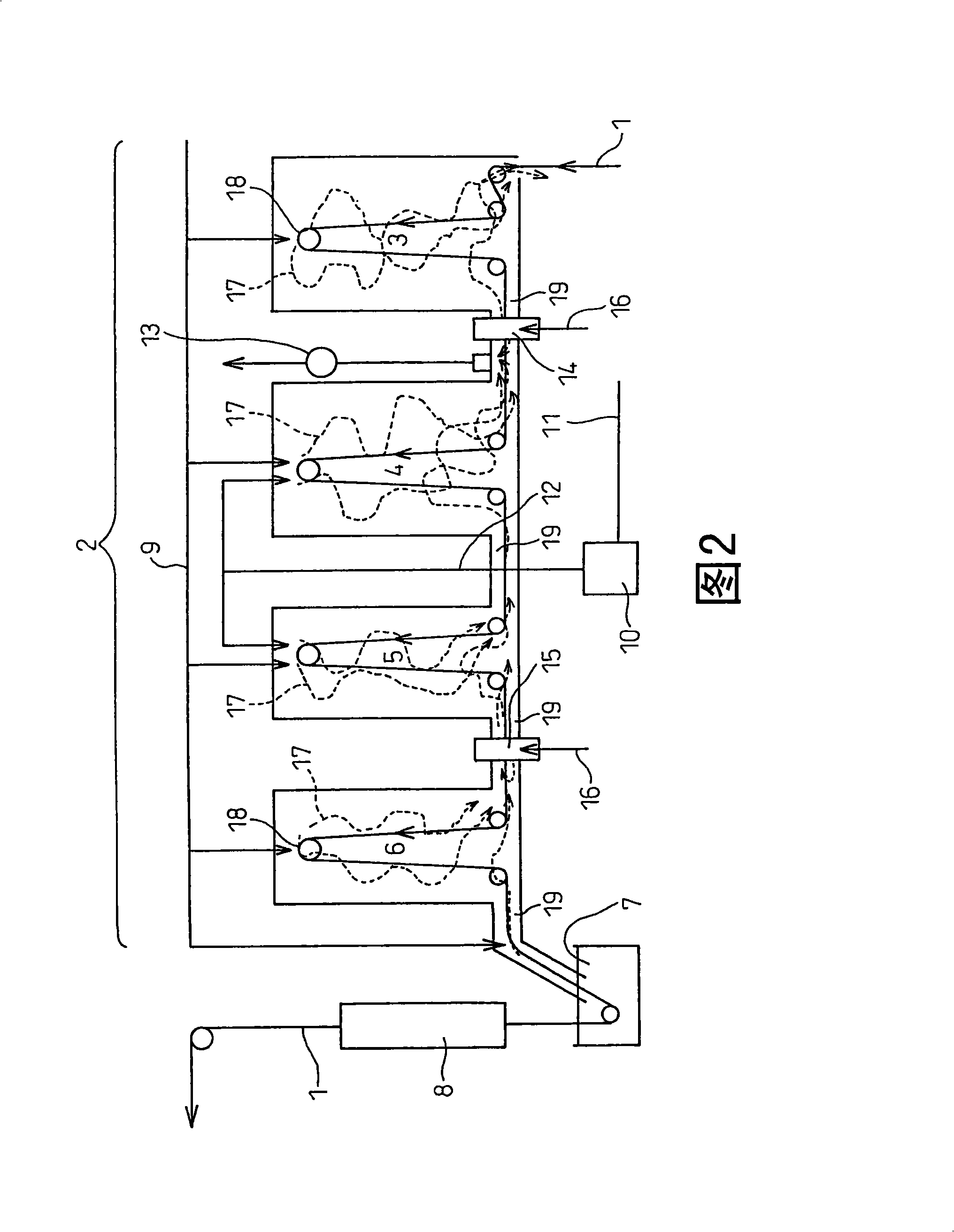
[0039] Fig. 2 shows the outline of one embodiment of the hot-dipping apparatus of the present invention. In this embodiment, the hot-dip coating device is composed of an annealing furnace 2, a hot-dip coating tank 7, and a heating belt front section 3, a heating belt rear section 4, a heat preservation belt 5, and a cooling belt 6 in the conveying direction of the steel plate 1. And alloying device 8. Each belt section 3, 4, 5, 6 of the annealing furnace is equipped with a roller 18 for continuously conveying the steel plate, and an opening 19 is arranged between each belt section, and the steel plate can pass through each belt section in the furnace. Each zone of the annealing furnace 2 is connected to a pipe 9 for introducing an atmospheric gas composed of hydrogen and nitrogen. The humidified nitrogen is obtained by blowing nitrogen gas from the nitrogen gas pipe 11 to the nitrogen humidifier 10 , and is introduced into the heating belt rear stage 4 and the heat preservati...


PUM


Abstract

A method of continuous annealing / hot-dipping using a hot-dipping apparatus having an annealing furnace in which a silicon-containing steel sheet is hot-dipped. In this method, the silicon contained in the steel is caused to undergo internal oxidation without undergoing surface oxidation to thereby avoid a decrease in deposit adhesion to the steel and a delay in galvannealing. Also provided is the apparatus for use in this method. The method of continuous annealing / hot-dipping employs an annealing furnace having a former heating zone, latter heating zone, heat retention zone, and cooling zone in this order and a hot-dipping bath. It comprises conducting annealing under the following conditions. In regions where the steel sheet has a temperature of at least 300 DEG C, the steel sheet is heated or kept hot by means of indirect heating. The atmosphere inside the furnace in each zone is an atmosphere consisting of 1-10 vol.% hydrogen and, as the remainder, nitrogen and unavoidable impurities. In the former heating zone, the steel is heated to a maximum temperature of 550-750 DEG C and the atmosphere is regulated so as to have a dew point lower than -25 DEG C. In the subsequent latter heating zone and heat retention zone, the dew point is regulated to from -30 DEG C to 0 DEG C. In the cooling zone, the dew point is regulated to below -25 DEG C.

Description

technical field [0001] The invention relates to a continuous annealing hot-dip coating method and a continuous annealing hot-dip coating device for Si-containing steel sheets. [0002] In addition, the hot-dip plating of the present invention does not specifically specify the type of plating metal, but includes hot-dip plating of zinc, aluminum, tin, and other metals or their alloys. Background technique [0003] In the case of hot-dip plating of metals such as zinc, aluminum, tin, or their alloys on the steel plate, the surface of the steel plate is usually degreased and cleaned, and the steel plate is annealed in an annealing furnace and the surface of the steel plate is activated by hydrogen reduction. After cooling to the specified temperature, the coating is performed by dipping in a hot-dip coating tank. The problem with this method is that when the steel sheet contains easily oxidizable metals such as Si and Mn, these easily oxidizable elements form individual or com...

Claims


Application Information

Patent Timeline
Patent Type & Authority Applications(China)
IPC IPC(8): C23C2/02C23C2/28C21D1/76C21D9/46
CPCC23C2/02C23C2/28C23C2/06C21D1/76C21D9/561C21D9/573C21D9/563C21D9/565C21D1/52C22C38/02C23C2/0222C23C2/0224C23C2/004C23C2/40C21D1/26
Inventor 冈田伸义
Owner NIPPON STEEL CORP
Why Eureka
Try Eureka