Polarizing plate having optical compensation layer, liquid crystal panel using the polarizing plate having optical compensation layer, liquid crystal display device, and image display device
An optical compensation layer, liquid crystal panel technology, applied in the directions of optics, optical elements, polarizing elements, etc., can solve the problems of white turbidity of retardation film, damage of retardation film, cumbersome quality management, etc., achieve high contrast, achieve contrast, inhibit The effect of color shift
Inactive Publication Date: 2008-10-15
NITTO DENKO CORP
View PDF26 Cites 10 Cited by
- Summary
- Abstract
- Description
- Claims
- Application Information
AI Technical Summary
Problems solved by technology
However, in this laminated retardation layer, since the liquid crystal monomer is dissolved in an organic solvent and directly coated on the retardation film, the retardation film will be corroded by the organic solvent, resulting in damage to the retardation film. , leading to the problem of white turbidity in the retardation film
In addition, when forming a phase difference layer composed of a liquid crystal layer by coating, since the phase difference in the thickness direction is controlled by the thickness of the coating film after drying, it is necessary to control the thickness of the coating film with high precision, and It is necessary to pay attention to the problem that the quality control in the work process such as air bubbles or foreign matter mixed into the coating film is cumbersome, resulting in a decrease in the yield of manufacturing.
Method used
View moreImage
Smart ImageViewing Examples
Examples
Embodiment 1
Embodiment 2
Login to View More PUM
| Property | Measurement | Unit |
|---|---|---|
| photoelasticity | aaaaa | aaaaa |
| thickness | aaaaa | aaaaa |
| thickness | aaaaa | aaaaa |
Abstract
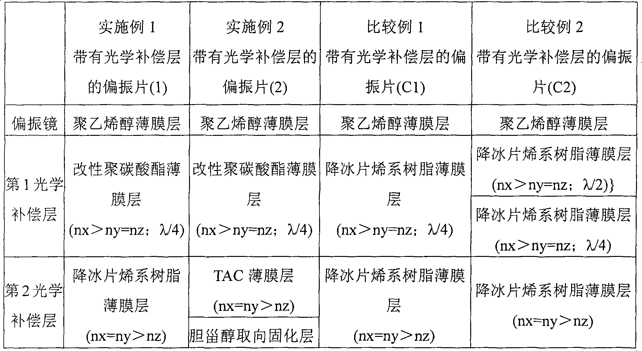
The present invention provides a thin polarizing plate having an optical compensation layer capable of improving visual angle characteristics, realizing a high contrast, preventing interference irregularities and thermal irregularities, suppressing a color shift, exhibiting a preferable color reproducibility, and effectively preventing light leak in the black display. It is also possible to provide a liquid crystal panel and an image display device using such a polarizing plate having an optical compensation layer. The polarizing plate having the optical compensation layer includes a polarizer, a first optical compensation layer, and a second optical compensation layer in this order. The first optical compensation layer has a refractivity distribution of nx > ny = nz and exhibits wavelength distribution characteristics in which the in-plane phase difference Re1 becomes smaller as the wavelength becomes shorter and the in-plane phase difference Re1 is 90 to 160 nm. The second optical compensation layer is a film layer having a refractivity distribution of nx = ny > nz, an in-plane phase difference Re2 0 to 20 nm, and a phase difference in the thickness direction Rth2 30 to 300 nm.
Description
Polarizing plate with optical compensation layer, liquid crystal panel using polarizing plate with optical compensation layer, liquid crystal display device, and image display device technical field The present invention relates to a polarizing plate with an optical compensation layer, a liquid crystal panel using the polarizing plate with an optical compensation layer, a liquid crystal display device, and an image display device. In more detail, the present invention relates to a polarizing plate with an optical compensation layer that contributes to thinning and can prevent hot spots, and can well prevent light leakage during black display, and the use of such a polarizer with an optical compensation layer. Liquid crystal panels, liquid crystal display devices, and image display devices of polarizers. Background technique As a VA-mode liquid crystal display device, in addition to a transmissive liquid crystal display device and a reflective liquid crystal display device,...
Claims
Login to View More Application Information
Patent Timeline
 Patent Type & Authority Applications(China)
IPC IPC(8): G02B5/30G02F1/1335G02F1/13363
CPCG02F1/133634G02B5/3033G02B5/305G02F1/133528G02B5/30G02F1/13363G02F1/1335
Inventor 首藤俊介冈田裕之千叶刚
Owner NITTO DENKO CORP
Features
- R&D
- Intellectual Property
- Life Sciences
- Materials
- Tech Scout
- Unparalleled Data Quality
- Higher Quality Content
- 60% Fewer Hallucinations
Learn More Browse by: Latest US Patents, China's latest patents, Technical Efficacy Thesaurus, Application Domain, Technology Topic, Popular Technical Reports.
© 2025 PatSnap. All rights reserved.Legal|Privacy policy|Modern Slavery Act Transparency Statement|Sitemap|About US| Contact US: help@patsnap.com


