Three axis optical fibre gyroscope inertia measurement unit integral structure

An inertial measurement unit and fiber optic gyroscope technology, which is applied to Sagnac effect gyroscopes and other directions, can solve the problem of large deviation between the inertial measurement unit mass center and the geometric installation center, affecting the temperature field distribution of the inertial measurement unit, and temperature compensation of unfavorable components. Control and other issues, to achieve the effect of being conducive to heat dissipation, temperature compensation and control, and small processing deformation

Inactive Publication Date: 2008-10-22
BEIHANG UNIV
View PDF0 Cites 56 Cited by
  • Summary
  • Abstract
  • Description
  • Claims
  • Application Information

AI Technical Summary

Problems solved by technology

The current integrated structure of the three-axis fiber optic gyro inertial measurement unit cannot meet the above requirements at the same time
That is, the existing technology has the following disadvantages: the overall weight is large, and the dynamic response characteristics are not good under shock and vibration environments; the center of mass of the entire inertial measurement unit deviates relatively from the geometric center, which seriously affects the dynamic measurement accuracy of the system; The complexity of the process and the arrangement of each component affect the temperature field distribution of the inertial measurement unit, which is not conducive to the temperature compensation and control of each component
[0004] The installation skeleton of the three-axis fiber optic gyro inertial measurement unit is a very impo

Method used


Image

  • Three axis optical fibre gyroscope inertia measurement unit integral structure
  • Three axis optical fibre gyroscope inertia measurement unit integral structure
  • Three axis optical fibre gyroscope inertia measurement unit integral structure

Examples


Embodiment Construction

[0043] The present invention is described in detail below in conjunction with accompanying drawing:

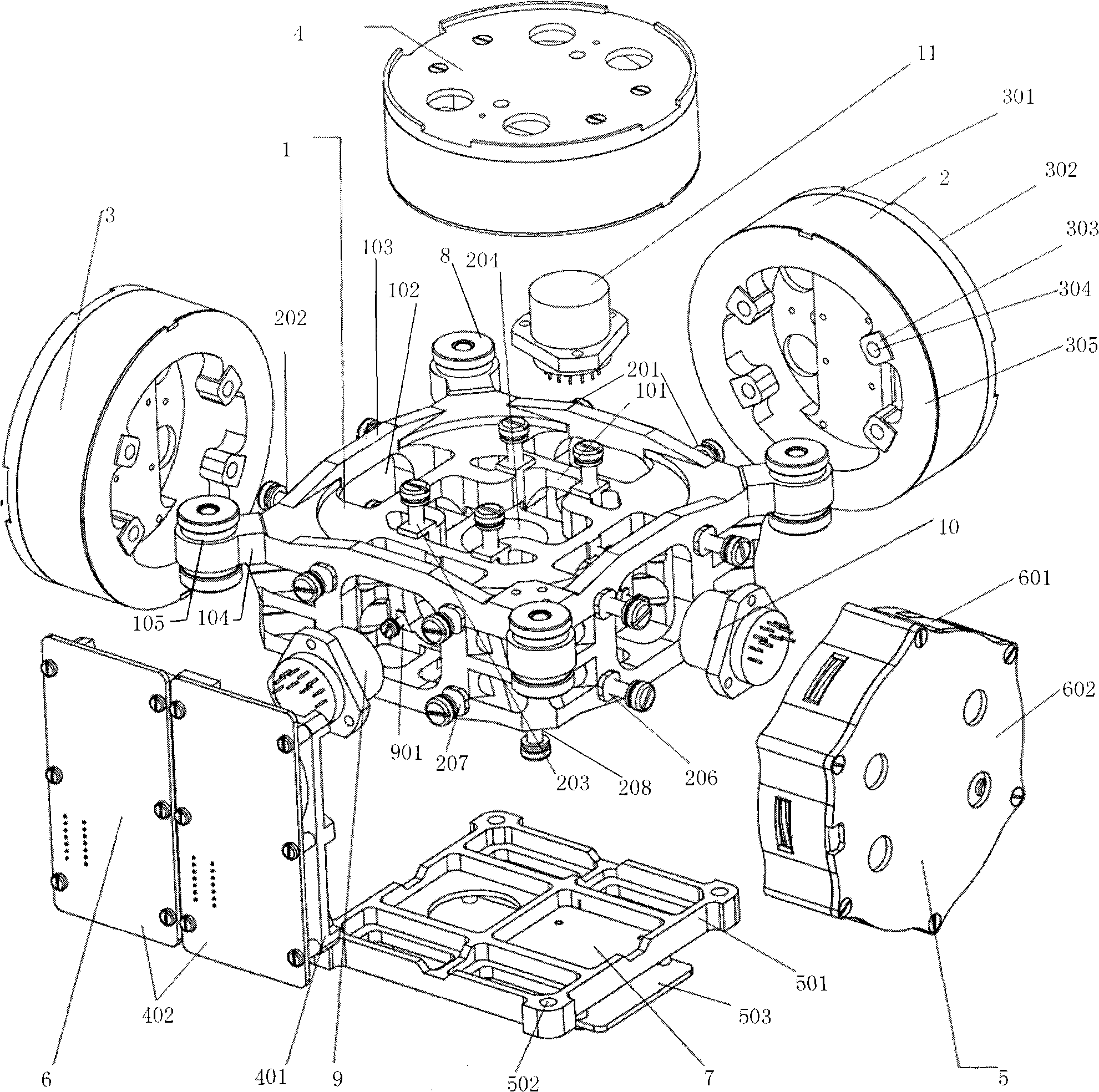
[0044] Such as figure 1 , Figure 7 , Figure 8 As shown, an integrated structure of a three-axis fiber optic gyro inertial measurement unit includes a mounting frame 1, and three fiber optic gyroscopes, three accelerometers, a light source, and a circuit board installed on it through multiple sets of mounting holes on the mounting frame 1 , Shock absorber 8.

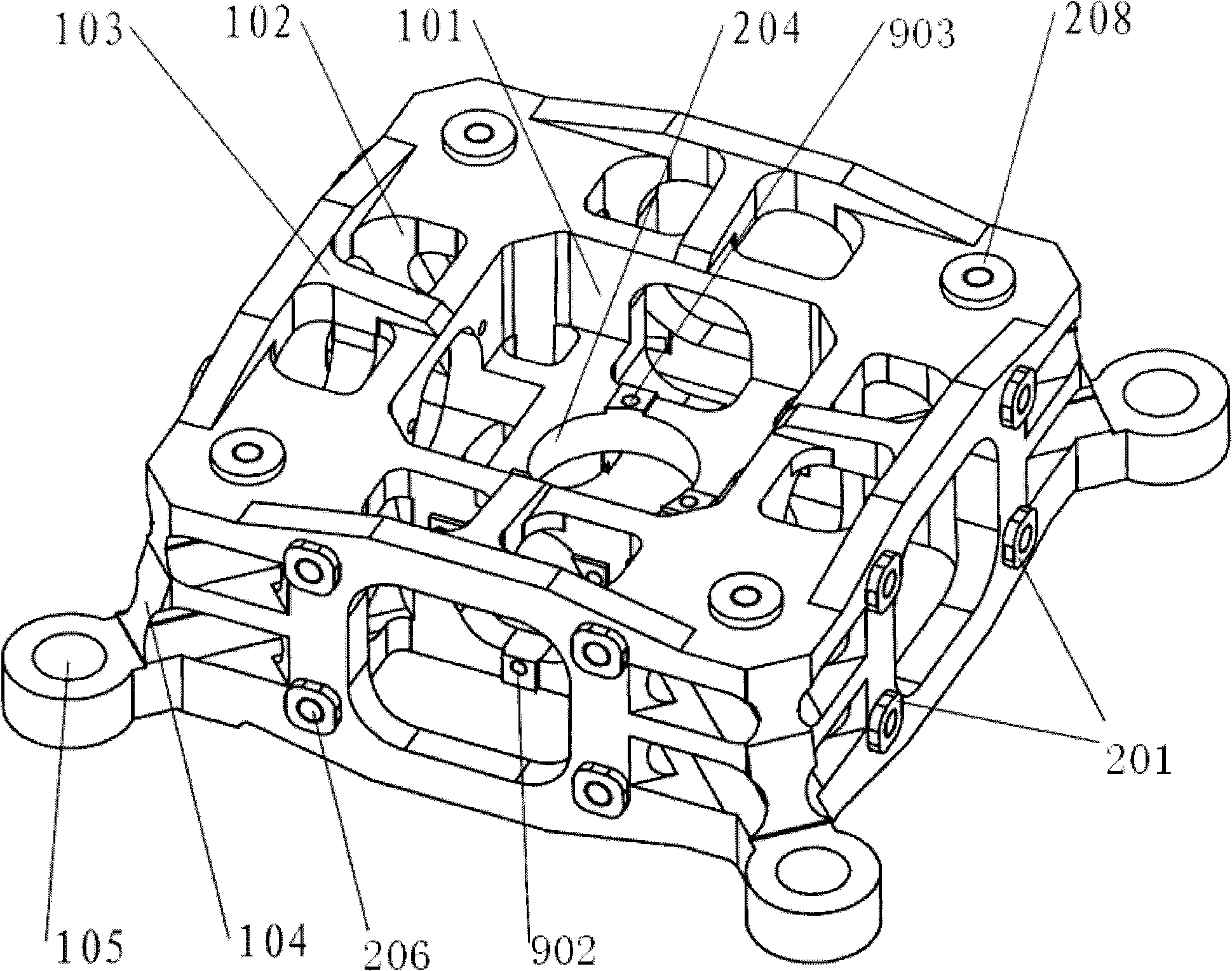
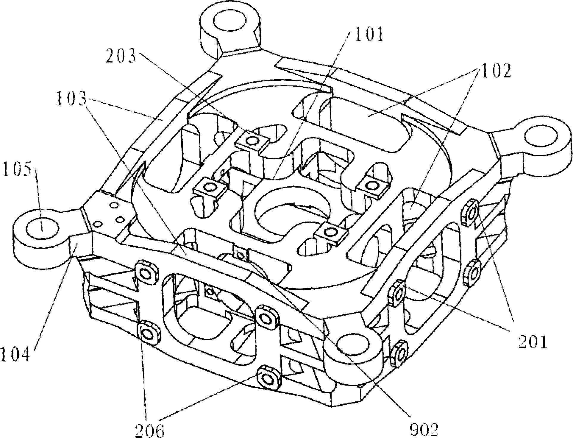
[0045] The mounting frame 1 adopts a hollow hexahedron frame structure, and each group of mounting holes is symmetrically arranged, and mounting bosses are provided on the positioning end faces of the mounting holes. The installation frame 1 adopts a hollow hexahedron frame structure, which not only ensures the overall rigidity and strength, but also makes the mass of the installation frame 1 very small. The symmetrical arrangement of each group of mounting holes is beneficial to minimize the deviation between the c...


PUM


Abstract

The invention relates to an integral structure of a triaxial optical fiber gyro inertia measuring unit, which comprises a mounting skeleton, three fiber optic gyro scopes, three accelerometers, a light source, a circuit board and a vibration damper. The mounting skeleton adopts a hollow hexahedron frame structure, each group of mounting holes are symmetrically arranged, and mounting lug bosses are arranged on the positioning end surface of the mounting holes. Three fiber optic gyro scopes form mutual space and are orthogonally arranged on the outer surface of the mounting skeleton, the light source and the circuit board are respectively arranged on the outer surface of the mounting skeleton which is corresponding to the three fiber optic gyro scopes, the three accelerometers form the mutual space and are orthogonally arranged on the inner surface of the mounting skeleton which is corresponding to the three fiber optic gyro scopes and near the geometric center of the mounting skeleton, and the vibration damper is arranged on the outer surface of the mounting skeleton. The measuring unit has the advantages that the quality is light; the degree of deviation between the mass center of an inertia measuring unit and the geometric mounting center is very small; the dynamic testing precision is high; the temperature field distribution of the inertia measuring unit is beneficial for the temperature compensation and control of each component, and the like.

Description

technical field [0001] The invention relates to the structure of a fiber optic gyro measuring device, in particular to an integrated structure of a three-axis fiber optic gyro inertial measurement unit. Background technique [0002] Fiber optic gyro is a new type of angular velocity sensor based on the Sagnac effect. Compared with mechanical gyroscopes, it has the advantages of all solid state, insensitivity to gravity, and fast startup; compared with ring laser gyroscopes, it has no high-voltage power supply. , no mechanical vibration and other advantages; in addition, it also has the advantages of light weight, long life and low cost, and has broad application prospects in military fields such as aviation, spaceflight, and navigation, as well as civil fields such as geology and oil exploration. The current typical structural form is: three independent single-axis fiber optic gyroscope subsystems are used to measure the angular velocity or position of the rotation axis of t...

Claims


Application Information

Patent Timeline
IPC IPC(8): G01C19/72
Inventor 章博张春熹张小跃杜新政宋凝芳林恒
Owner BEIHANG UNIV
Why Eureka
Try Eureka