Thermal coupling multilevel pulsatron refrigerating machine
A pulse tube refrigerator and thermal coupling technology, applied in refrigerators, refrigeration and liquefaction, compressors, etc., can solve the problems of increasing heat conduction loss, low refrigeration temperature, pressure amplitude loss, etc., and reduce pressure loss and heat conduction loss. , low cooling temperature, the effect of improving efficiency
- Summary
- Abstract
- Description
- Claims
- Application Information
AI Technical Summary
Problems solved by technology
Method used
Image

Examples
Embodiment 1
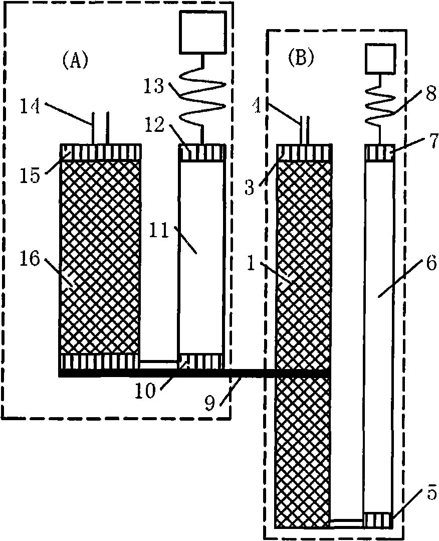
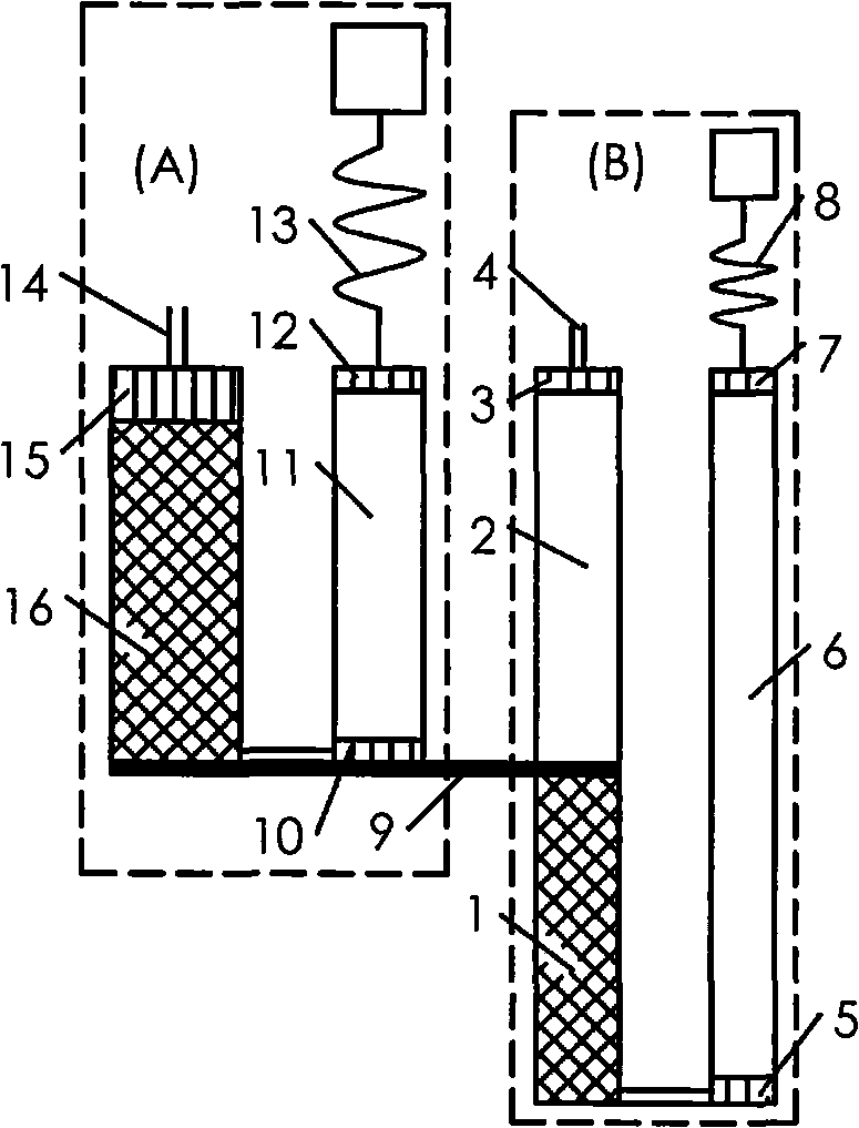
[0017] Example 1: figure 2 It is a structural schematic diagram of a thermally coupled multi-stage pulse tube refrigerator (two-stage thermally coupled pulse tube refrigerator) of the present invention. It can be seen from the figure that the precooling pulse tube refrigerator A has a single-stage structure, and the low-temperature pulse tube refrigerator B’s low-temperature pulse tube refrigerator regenerator 1 and the low-temperature pulse tube refrigerator room temperature heat exchanger 3 are connected with a low-temperature pulse tube Refrigerator thermal buffer tube 2; the precooling pulse tube refrigerator cold head 10 of the precooling pulse tube refrigerator A passes through a thermal bridge 9 and the low temperature pulse tube refrigerator regenerator 1 close to the low temperature pulse tube refrigerator thermal buffer One end of the tube 2 is connected; the low-temperature pulse tube refrigerator phase modulation component 8 of the low-temperature pulse tube refri...
Embodiment 2
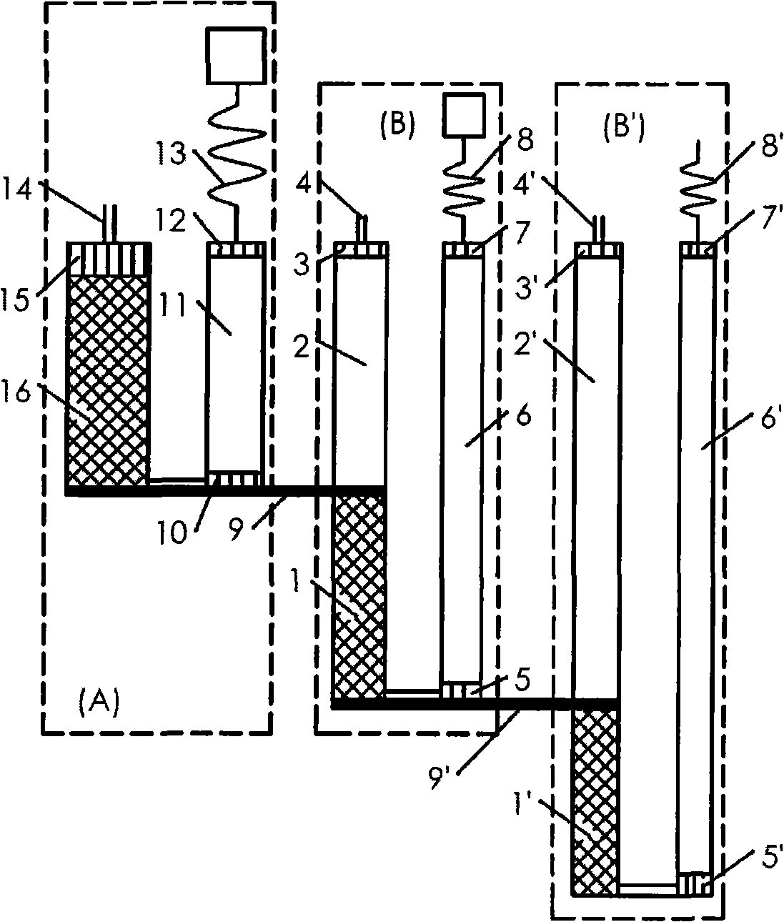
[0019] Example 2: image 3 It is a structural schematic diagram of a thermally coupled multi-stage pulse tube refrigerator (three-stage thermally coupled pulse tube refrigerator) of the present invention. Depend on image 3 It can be seen that it is mainly composed of a pre-cooling pulse tube refrigerator A and the first and second two low-temperature pulse tube refrigerators B and B'; the pre-cooling pulse tube refrigerator A is a single-stage structure, and the low-temperature pulse tube refrigerator B The heat buffer 2 of the low-temperature pulse tube refrigerator is connected between the regenerator 1 of the low-temperature pulse tube refrigerator and the room temperature heat exchanger 3 of the low-temperature pulse tube refrigerator, and the second low-temperature pulse tube refrigeration unit of the second low-temperature pulse tube refrigerator B' The thermal buffer pipe 2' of the second low temperature pulse tube refrigerator is connected between the regenerator 1' ...
Embodiment 3
[0021] Example 3: Figure 4 It is a structural schematic diagram of a thermally coupled multi-stage pulse tube refrigerator (four-stage thermally coupled pulse tube refrigerator) of the present invention. Depend on Figure 4 It can be seen that it is mainly composed of a precooling pulse tube refrigerator A and a low temperature pulse tube refrigerator B. , the pre-cooling pulse tube refrigerator A is a three-stage gas-coupled pulse tube refrigerator, and the low-temperature pulse tube refrigerator B’s low-temperature pulse tube refrigerator regenerator 1 and the low-temperature pulse tube refrigerator room temperature heat exchanger 3 are connected with a low-temperature Pulse tube refrigerator heat buffer 2; the precooling pulse tube refrigerator cold head 10 of precooling pulse tube refrigerator A passes through a thermal bridge 9 and the low temperature pulse tube refrigerator regenerator 1 close to the heat of the low temperature pulse tube refrigerator One end of the b...
PUM
 Abstract
Description
Claims
Application Information
 - Generate Ideas
- Intellectual Property
- Life Sciences
- Materials
- Tech Scout
- Unparalleled Data Quality
- Higher Quality Content
- 60% Fewer Hallucinations
Browse by: Latest US Patents, China's latest patents, Technical Efficacy Thesaurus, Application Domain, Technology Topic, Popular Technical Reports.
© 2025 PatSnap. All rights reserved.Legal|Privacy policy|Modern Slavery Act Transparency Statement|Sitemap|About US| Contact US: help@patsnap.com