Emission method and device

A technology of launching device and spinner, which is applied to weapons without explosives, throwing weapons, offensive equipment, etc., can solve the problems of high power, long range, short mover, etc., and achieve powerful effects

Inactive Publication Date: 2008-10-29
孟英志
View PDF0 Cites 8 Cited by
  • Summary
  • Abstract
  • Description
  • Claims
  • Application Information

AI Technical Summary

Problems solved by technology

Moreover, the stator of the electromagnetic catapult is very long (about 130 meters), and the mover (equivalent to the rotor of the rotating motor) is short (less than 10 meters long in the track), so the utilization rate is not high when it is used, and the magnetic gap when the rotor passes It also has a certain influence on the magnetic field density
[0017] Fourth, the projectile has a large initial velocity, a long range, and great power
[0020] However, the research work on electromagnetic launch technology may continue for more than 20 years, because there is no warship that can generate and store the electrical energy required for firing

Method used


Image

  • Emission method and device
  • Emission method and device
  • Emission method and device

Examples


Embodiment 1

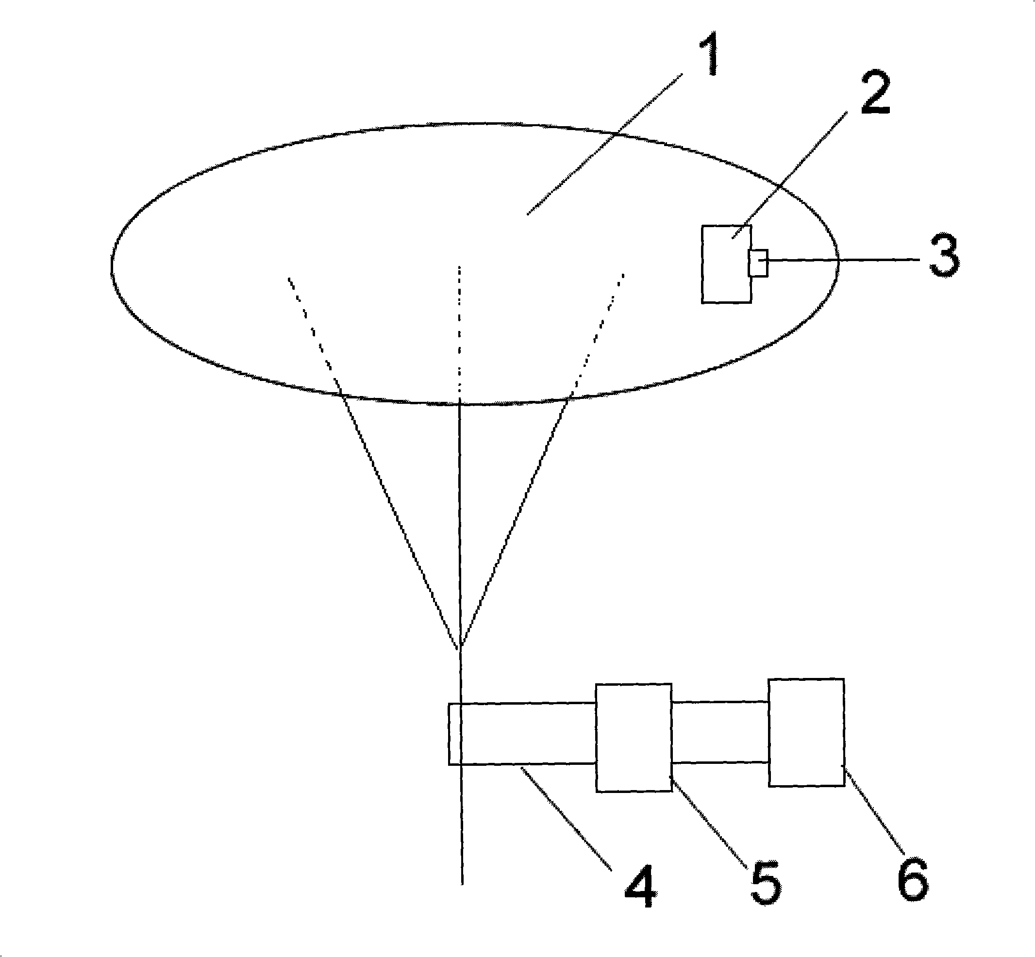
[0046] Such as figure 1 As shown, the rotator 1 adopts a light alloy disc with a radius of 30 meters, which is firmly supported by a support frame below, and the total weight can be controlled below 200 tons. The aircraft 2 is fixed on the edge by the controller 3. The controller adopts wireless The remote controller can also use a photoelectric controller. The controller can control the take-off direction and angle of the aircraft at any time. The motor 5 can make the rotator rotate through the transmission system 4. The transmission system can be a chain or a gear or a gearbox. Assuming that the weight of the aircraft is 50 Ton below, then select the generating set 6 of 2000 kilowatts-5000 kilowatts for use, can satisfy the take-off condition of 1 or more aircrafts. When in use, the power supply drives the rotator to rotate through the motor. When the rotating speed of the rotator exceeds 30 rpm, the take-off speed of the aircraft can be reached, and the controller is turned...

Embodiment 2

[0048] Such as figure 1 As shown, if the object to be launched is a missile or other objects with different purposes, the rotator can be designed and motors with different rotating speeds can be selected according to different purposes, which is easily done by those skilled in the art. Assuming that a 50kg missile is launched, a rotator with a radius of 5-10 meters can be used, and the motor can use 80,000 rpm, so the launch speed can reach more than 30km / s, and its power is enough to destroy any target in outer space. The object to be launched can be placed in the desired position of the rotator according to the specific situation. The launch timing and direction of the missile can be controlled at any time through the controller.

Embodiment 3

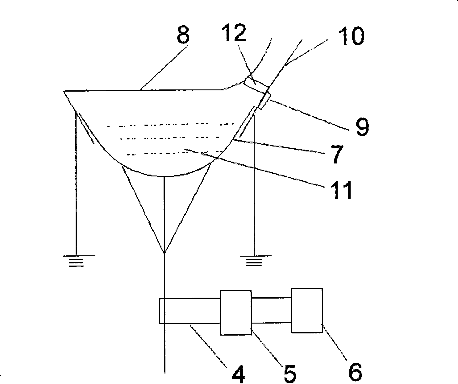
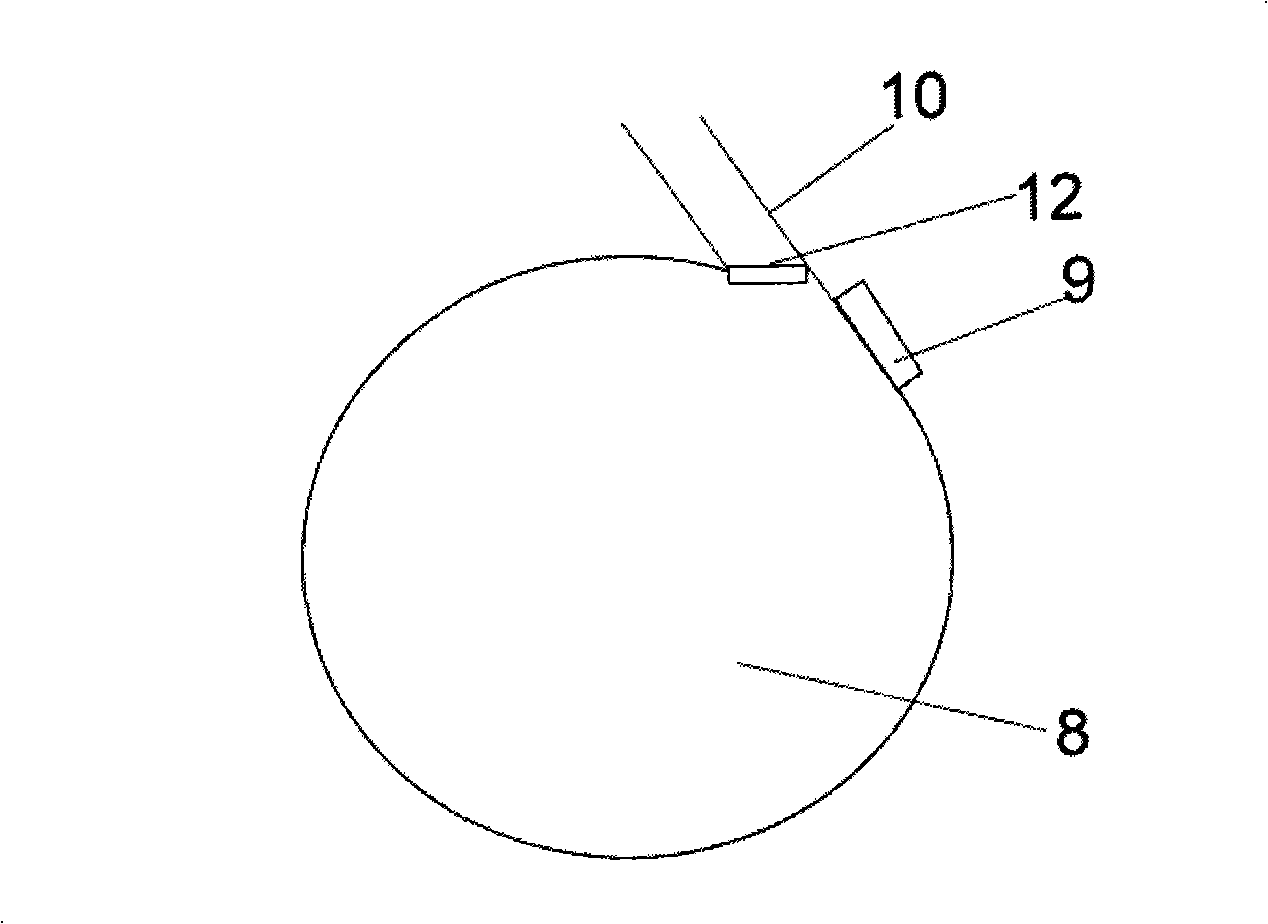
[0050] Such as figure 2 , image 3 As shown, the rotator adopts a concave body 7, and the rotator cover 8 is fixed above the concave rotator by a fixed bracket and does not rotate with the rotator. There is a slight gap between the rotator cover 8 and the rotator 7 so as not to affect the rotator 7. Rotation is as the criterion, and outlet 10 is arranged on rotator cover 8, and degausser 9 is arranged at the outlet, and outlet and degausser can be one group, also can be more than one group. The concave rotator 7 and the rotator cover 8 adopt super-strong magnetic materials, and there are steel projectiles 11 in the concave rotator 7, so that the concave rotator 7 and the rotator cover 8 have a magnetic attraction effect on the projectiles. Assuming that the concave rotator 7 adopts a radius It is a parabolic structure of 1 meter and a depth of 1 meter, with 100,000 grains of 2-gram heavy projectiles inside, a motor of 80,000 rpm, a generator set of 2000 kilowatts-5000 kilowa...


PUM


Abstract

The invention discloses a launching method and a launching device. A method of rotating a rotator is adopted. The launching method is mainly used for launching a carrier aircraft and various spacecrafts; moreover, the launching method can be used for launching various missiles and high-energy weapon systems. The invention manages to overcome the existing problems of various catapults for aircraft carriers based on a novel concept. Meanwhile, compared with an electromagnetic rail gun, the launching device has no need for super-energy launch and manages to solve the power problem which is difficult to overcome for the electromagnetic rail gun, and the power of the launching device far exceeds that of the an electromagnetic rail gun, and creates the future of a novel weapon system.

Description

1. Technical field [0001] The invention belongs to the launching method and device of aircraft carrier-based aircraft, and can also be applied to the launching method and device of missiles, spaceships, rockets, satellites, etc., and can also be applied to the method and device of launching high-energy weapons such as artillery shells and bullets. 2. Background technology [0002] On an aircraft carrier, in addition to helicopters, short-distance take-off and landing, and vertical take-off and landing aircraft, if you want to take off a fighter jet of a certain weight, you must use a catapult to take off or use a ski jump to take off. The device is actually a steam piston with a large opening. The piston ring receives the force of the steam from the inside of the piston to the outside through the sealing knife, pushing the ejection front wheel and realizing the take-off of the fighter. In order not to leak steam, the opening must be sealed with a sealing strip. When the seal...

Claims


Application Information

Patent Timeline
Patent Type & Authority Applications(China)
IPC IPC(8): F41B3/04
Inventor 孟英志
Owner 孟英志
Why Eureka
Try Eureka